


Open Loop Design
Open Loop Fluxgate Magnetometers
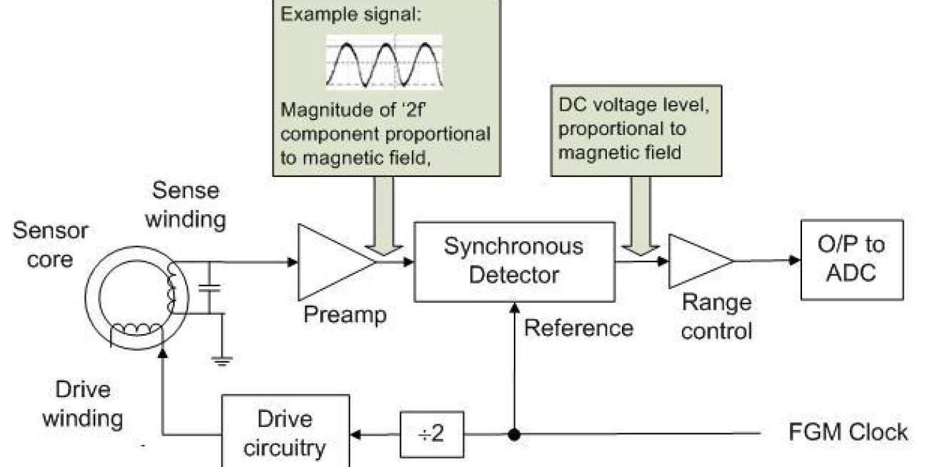
Open Loop Fluxgate magnetometers are rarely used, because of the linearity advantages of the Closed Loop design, however, the basis for the method of extraction of the magnetic field is the same in each case, and it can be easier to see how the design works in the open loop case. The block diagram below shows the basic components of an open loop fluxgate magnetometer using analogue field extraction.
-
The magnetometer is driven with a square wave (typical frequency tens of kHz) through the drive winding.
-
As discussed on the fluxgate magnetometer page, in the presence of an external magnetic field, a small, field proportional voltage is induced in the sense winding at twice the drive frequency, the so-called '2f' frequency.
-
In this design, this small induced voltage is amplified by tuning the sense winding to the '2f' frequency using a capacitor in parallel to the sense winding, and by then passing the voltage through a pre-amplifier. An example of the signal at this point in the circuit is shown in the diagram below.
-
The synchronous detector, compares the phase of the amplified '2f' signal with a reference square wave to determine the sign of the measured field, and then rectifies it to dc, such that the magnitude of the produced dc voltage is proportional, in both sign and magnitude, to the external magnetic field in the sense direction.
Synchronous Detector Inputs and Outputs Input Reference and '2f' signals Phase Relationship Field Direction Output of Synchronous Detector 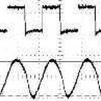
In phase Positive Positive DC voltage level proportional to magnitude of 2f component 
Out of phase Negative Negative DC voltage level proportional to magnitude of 2f component