


Imaging and optical diagnostics
Imaging and optical diagnostics
High resolution 3D DIC for dynamic strain measurements
- Thomas White (RA)
- Jack Patten (PhD student)
- Gilles Tahan (ERASMUS student)
- Daniel Eakins
A high resolution digital image correlation system for use in high strain rate experiments was developed for the miniature Split Hopkinson Pressure Bar (m-SHPB) as part of the HexMat EPSRC programme grant. The system is capable of providing full 3D surface deformation with a single high frame-rate camera. Utilising open-source camera calibration and two-dimensional digital image correlation tools within the MATLAB framework sub-micron resolution is demonstrated. A displacement calibration demonstrates accuracy of beyond 1 micron matching that achievable with commercial software.
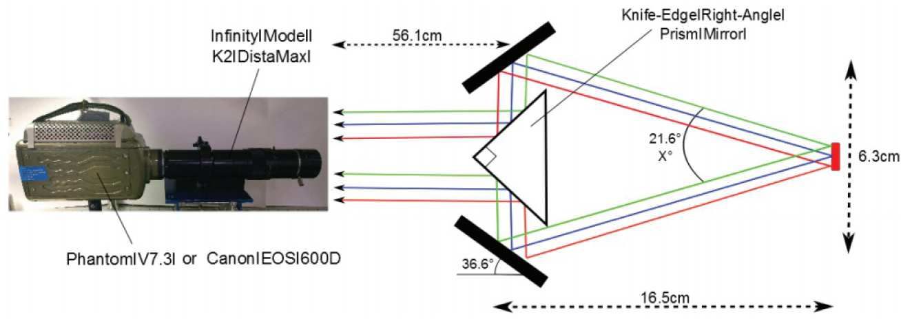
The stereoscopic system uses mirrors and a prism (see figure 11) to simultaneously view the target from two angles on a single high-speed camera, thus allowing the reconstruction of 3D surfaces. Beyond reducing the cost of the system this also overcomes synchronisation problems associated with multiple cameras; a challenging task in high strain rate experiments.
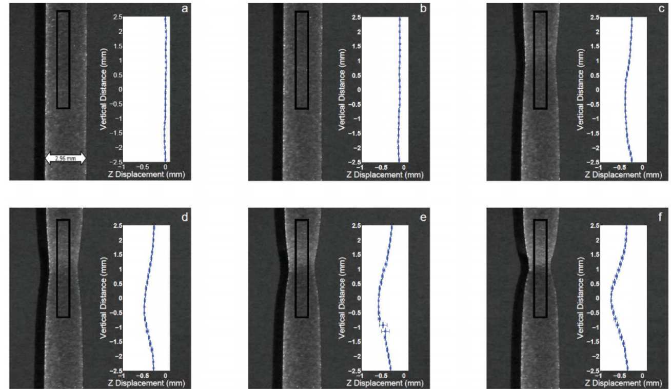
A series of tests of the imaging system, analysis code and speckle pattern application have been performed, the results of which demonstrate a sub-pixel level of precision. The imaging system is compact and mobile, allowing it to be fielded on a range of dynamic experiments, and has already been used on the m-SHPB, manuallydriven deformation tests and samples subjected to uniaxial loading via an Instron machine, see figure 12. The experimental and analytical methods are robust and require only that a sample’s surface displays a speckle pattern on the scale of interest.
This work was carried out in collaboration with Gilles Tahan, an ERASMUS student from ENSTA, Brest in France.
Figure 11: Schematic of experimental layout demonstrating how a single high frame-rate camera can be used to perform stereoscopic imaging.
Figure 12: Evolution of tensile specimen subjected to a constant velocity of 1 mm/ minute. The insert shows the out-ofplain surface position averaged across the highlighted region. Data is shown for times (a) 503s (b) 675s (c) 783s (d) 795s (e) 807s (f) 819s corresponding to a global strain of (a) 24.8% (b) 33% (c) 38.6% (d) 39.2% (e) 39.8% (f) 40.4%. These times were chosen to cover the largest out-of-plane motion. Error bars represent standard deviation across the width of the sample.
Shock compression of anisotropic dielectrics
- Gareth Tear (PhD student)
- David Chapman (RA)
- Daniel Eakins
- William Proud
Anisotropic materials show behaviour that is directionally dependent. This behaviour is not limited to simple variations in shock speed, and can include the generation of motion transverse to the shock wave. Optical properties are a function of this complex behaviour and optical measurements are being developed to measure this.
We have developed a combined optical ray tracing and characteristics model that offers predictive capabilities for the optical behaviour of complex anisotropic crystals under shock compression. The optical model is three dimensional and capable of resolving arbitrary orientations of biaxial materials. This has been used to generate predictive polarimeter signals for plate impact experiments on homogenous anisotropic dielectrics including calcite and sapphire.
Previous experimental work on the ISP’s meso scale gas gun has demonstrated the capabilities of a high-speed polarimeter. This has been employed recently on the 100 mm bore gas gun to verify the predictive capabilities of the model.
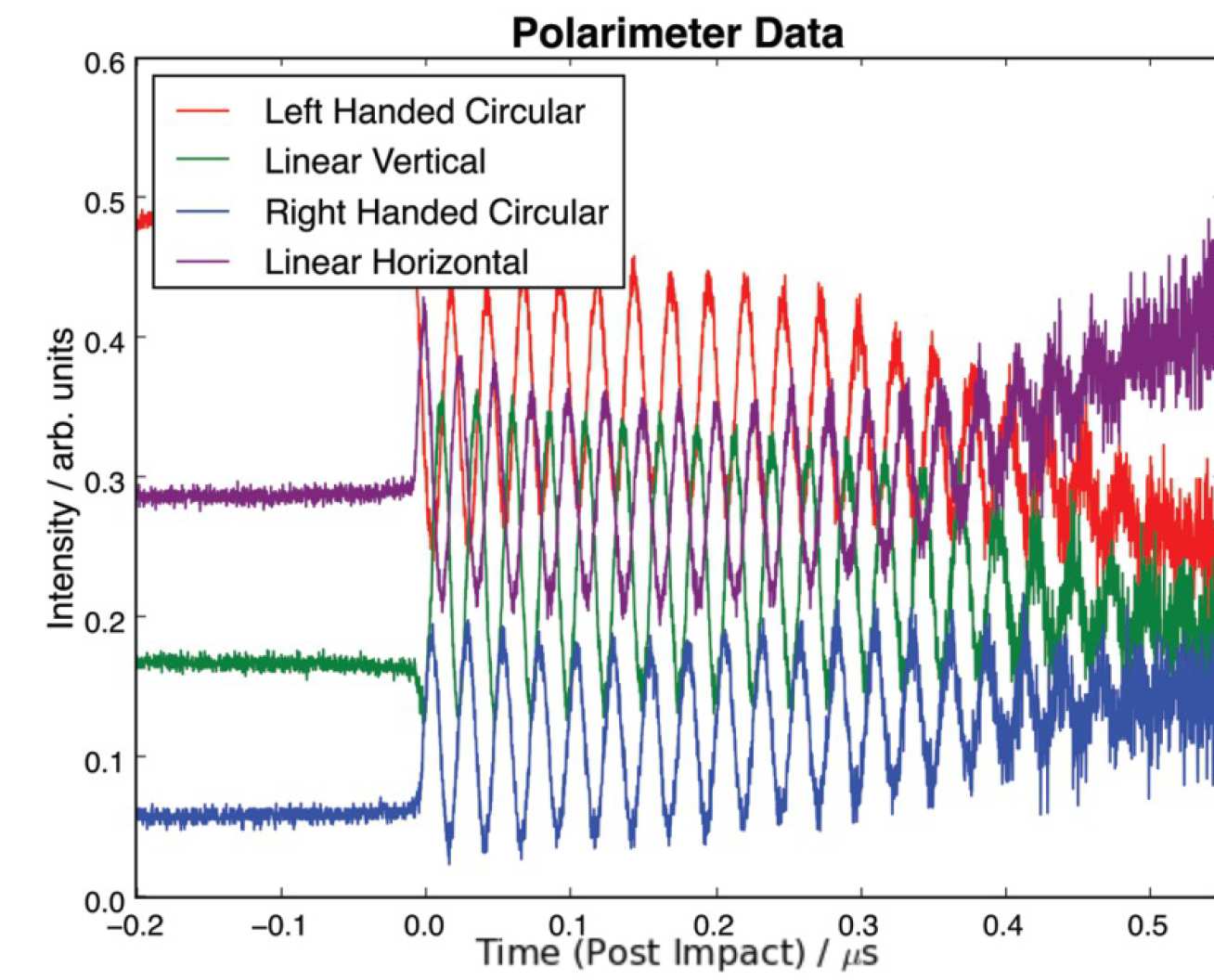
Figure 19: Polarimetery data from 206 m/s impact of magnesium and a-cut calcite. The four channels are horizontal and vertical linearly polarised light (S/P), and left and right handed circular polarised (L/RHC) light. Data was acquired for 550 ns, though shock breakout at the rear surface occurred at 1.1 microseconds. The beat frequency is caused by Fresnel reflection at the shock front.
Reflectance thermometry system for determination of spatial temperature variations in dynamic compression experiments
- Jasmina Music (PhD student)
- David Chapman (RA)
- Daniel Eakins
The measurement of temperature represents a long-standing challenge within the field of high-pressure science. Furthermore, in dynamic experiments where expected temperatures are below 1000 K passive diagnostic techniques such as optical pyrometry become infeasible due to the transit states that exist. Reflectance thermometry, an active diagnostic technique that has been recently reported in literature, is a promising time-resolved temperature measurement technique employing embedded optical sensors in the form of thin gold films.
Since it is known that structural imperfections of materials and the onset of dynamic phenomena cause locally nonuniform temperature distributions, in the present project a reflectance thermometry diagnostic will be adapted and its viability tested for the purpose of spatially-resolved temperature measurements.
A critical component of the reflectance thermometry technique is the optical characterisation of the embedded sensors. The reflectance measurement system will be used for reflectance spectroscopy of the gold films as a function of temperature from ambient conditions to 800 K, and as a function of pressure using a diamond anvil cell in collaboration with Simon MacLeod (AWE). The experimental data obtained at ambient pressure will be compared with commercial ellipsometry and initially be fitted to a Drude-Lorentz model for the optical properties of metals paving the way for the calibrated films to be used during future dynamic compression experiments.
Optimisation of the optical imaging system and image analysis for symmetric Taylor Impact experiments
- Stefan Heufelder (MSc student)
- David Chapman (RA)
- William Proud
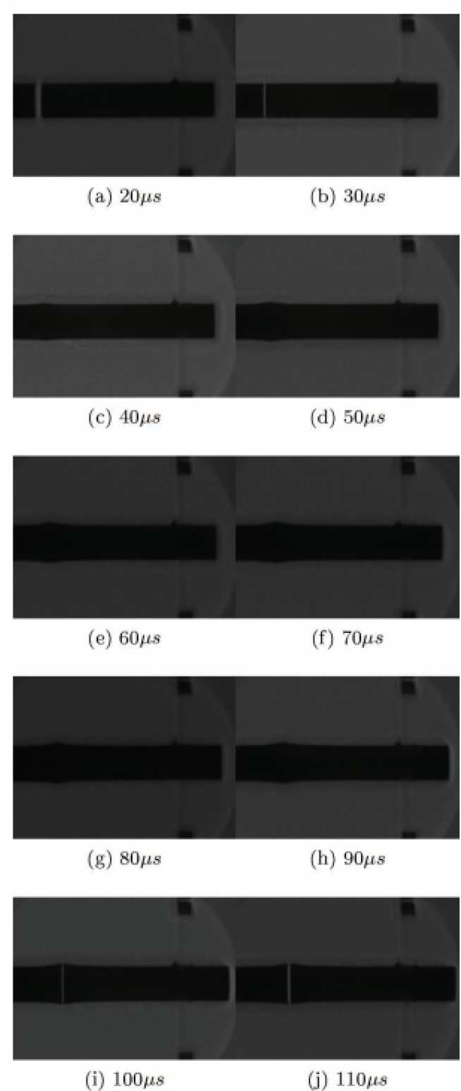
The Taylor impact test, involving the normal incidence impact of a cylindrical specimen on a rigid anvil was originally devised by G. I. Taylor to estimate dynamic yield strength of solids. Although rarely used for this purpose today, the Taylor impact test is still widely used as a means of validating constitutive material models used in finite element simulations as a result of the complex stress states, and range of strain rates accessed during a single experiment. The modern implementation of a Taylor impact test often involves the rod on rod geometry to reduce frictional effects and issues surrounding non-ideal anvils. In addition, modern time-resolved diagnostics such has high-speed photography or velocity-interferometry are used to monitor the damage evolution during the test for direct comparison with finite element simulations. In particular, deformation profiles captured using high-speed photography have been widely used to validate material models by direct comparison with simulated specimen profiles. However, uncertainties in the experimentally measured deformation profiles arising from imperfections in the imaging system are often not rigorously quantified. To address this shortcoming, an MSc research project which developed a robust method of characterising and correcting imaging imperfections, whilst also determining the optical resolution of a given imaging system was completed. The developed methodology involved the capture of a series of static calibration images, which were subsequently used in an automated MATLAB routine to facilitate the subpixel level correction of a dynamic sequence obtained using the Invisible Vision UHSi high speed-framing camera. As a demonstration, a small series of Taylor impact experiments, involving the symmetric impact of 13 mm diameter, 65 mm length copper specimens was performed on the ISP mesoscale gas gun. Figure 30 presents an example image sequence obtained using the UHSi high-speed framing camera, triggered to capture the deformation evolution in the specimen during the impact event. A novel edge detection algorithm was also developed in MATLAB to facilitate the sub-pixel identification of the specimen edge from the silhouette images for accurate specimen profile determination. The resulting specimen profile is overlaid on the dynamic image sequence in figure 30. The developed experimental methodology enabled the accurate determination of both specimen profile and quantification of experimental uncertainty, paving the way for more faithful constitutive model validation using the Taylor Impact technique.
Figure 30: Corrected high-speed image sequence of a symmetric Taylor impact test using copper specimens impacted at 230 m/s. Interframe and exposure times were 10 us and 0.5 us respectively.