Introduction to TAFTS Engineering
The detailed design and engineering was carried out by Dr A. Canas and Dr J. Murray, drawing on considerable local expertise in FTS theory in the Spectroscopy Group in the form of the late Dr R.C.M. Learner and Dr A.P. Thorne (retired). A collaboration has been entered into with the Astrophysics group of Queen Mary College (University of London), led by Prof. P. Ade (now at Cardiff University), who provided the TAFTS team at Imperial College with the polarising copper grids, shortwave filters and photo-conductor crystals used in the instrument. The project has also been favoured by the support of the Met-Office, with valuable resources in the form of flight hours, integration costs and support personnel, and financial support from NERC.
The TAFTS instrument has been fully modelled using AutoCad2000 by our resident cad specialist, Andy Rochester (main physics workshop). Andy's advice, redesign and manufacture of optical mounts used in TAFTS was instrumental in keeping the instrument within the design specifications for size. The detector and optical arrangement within the cryostat has itself been a major challenge to conceive, the challenge of manufacturing these components fell to the optical workshop personnel particularly Paul Brown.
TAFTS has been almost completely built within the Imperial College Physics departments workshops. Much additional effort has gone in from others in these workshops including, Ray Swain, Alan, Roger, John and Fred.......
It is possible to break TAFTS down into four separate units, the Pointing Optics, Interferometer, Cryostat and Control Box. Each link below will take you onto separate descriptions of these units.
See also Dimensions
TAFTS Engineering
- The Pointing Optics
- The Interferometer
- Cryogenic Optics and Detector System
- Electronic Control System
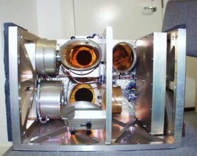 The pointing optics unit contains two steerable mirrors (driven by stepper motors), three fixed (folding) mirrors to direct radiation into the interferometer, four blackbodies for calibration, a ambient temperature probe and the associated control electronics for the blackbodies. The figure below shows the pointing optics demounted from the rest of the instrument, the view is from the interferometer side, and the viewers eye is roughly aligned with the beam splitter.
The blackbody visible in the top mirror is actually situated diagonally down and right in the image (which is seen side-on near the centre line). The image is diverted into the interferometer by the steering mirror (the lower vinetted image of the blackbody is reflected of this steering mirror) and a periscope arrangement of folding mirrors. The steering mirror can be steered to view this (ambient temperature black body), a hot blackbody, or look downward at the up-welling radiation from the atmosphere.
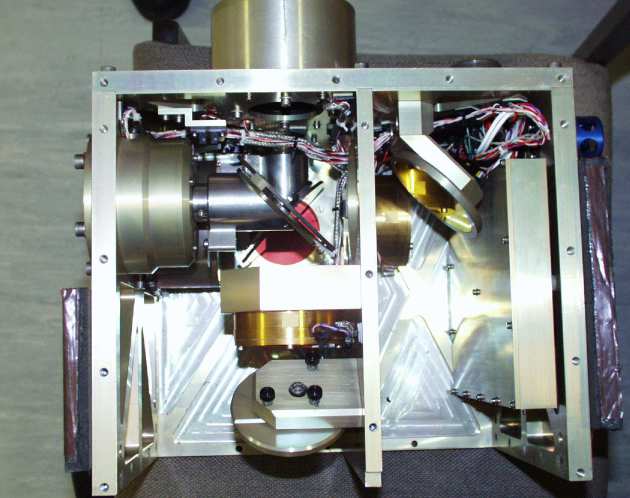 The second view of the pointing optics unit is from above, roughly above the up-looking port of the instrument. The two steering mirrors can be seen orthogonal to each other and edge-on to our view. Above the top steering mirror (from our perspective), and external to the unit wall, is a housing containing a heated blackbody, below the steering mirror is an ambient temperature blackbody. The steering mirror can be turned to view either of these or the down-welling radiation from the atmosphere. This radiation is steered into the interferometer via the steering mirror a folding mirror to the right and another folding mirror which is actually housed within the interferometer unit.
A little more on the role of the blackbodies
The blackbodies are used to calibrate the instrument and put the measured atmospheric radiances onto a meaningful scale. Easily said, but we can assure you that this is not a simple task and probably accounts for the majority of poor cross comparisons between different instruments.
We have to calibrate because the radiances that the instrument measures are affected by the instrument itself. The mirrors used are not 100% efficient (i.e. they will not have 100% reflectivity and they will absorb and scatter some of the incoming radiation). The same is true of all the other optical components, ie the window material (not perfectly transmissive), the photon-conductor detectors will also not be 100% efficient, the list goes on. To add to the complexity of the task we have to take into account that these components spectral response will vary greatly.
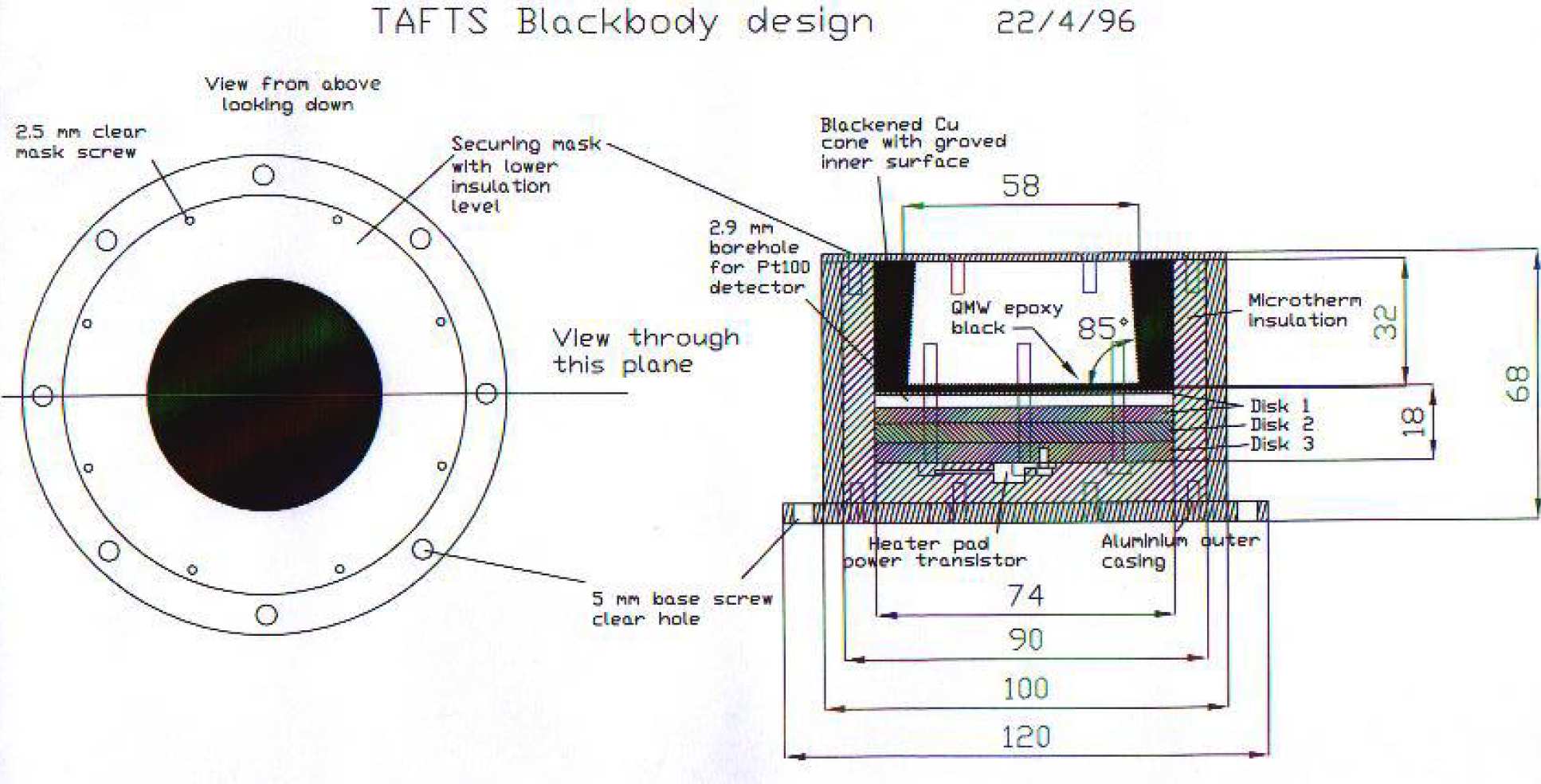 Above: On-board blackbody design (space restrictions meant that these had to be kept compact). These blackbodies are calibrated on the ground against an 'absolute target'
The above is simply a multiplicative factor, we also have to worry about the additive factors. This comes from the simple fact that, for instance, the mirrors do have a small emissivity and will therefore themselves radiate. The blackbodies do have a small reflectivity (specular and diffuse) and the radiation from the surrounding walls etc.. can, therefore, be reflected into the field of view. The effect of these 'Stray sources' depends on where they are situated. If they are on the input side of the interferometer the signal will be modulated by the interferometer and we will observe the spectral signature, this needs to be characrterised and subtracted from the final spectrum. If the stray source is after the beamcombiner then the signal will not be modulated by the interferometer, it will be seen as an additional off-set to the interferogram and will not contribute to the spectral signature, but will add additional noise to the system.
TAFTS can take advantage of it's differential measurement capability to reduce much of the above problems. Because care has been taken to balance the number of reflections in each input, any spectral signature emitted from these components will, if the mirrors are identical and clean, cancel out in the observed spectrum (if the optical path through any absorber is equal). The signal will still be detected in the interferogram off-set, but will, like the unmodulated stray signal, just add noise to the final spectrum.
 The system is based upon a polarising interferometer of the Martin-Puplett type in which radiation from both upward-looking and downward-looking input ports are combined via an input polariser.
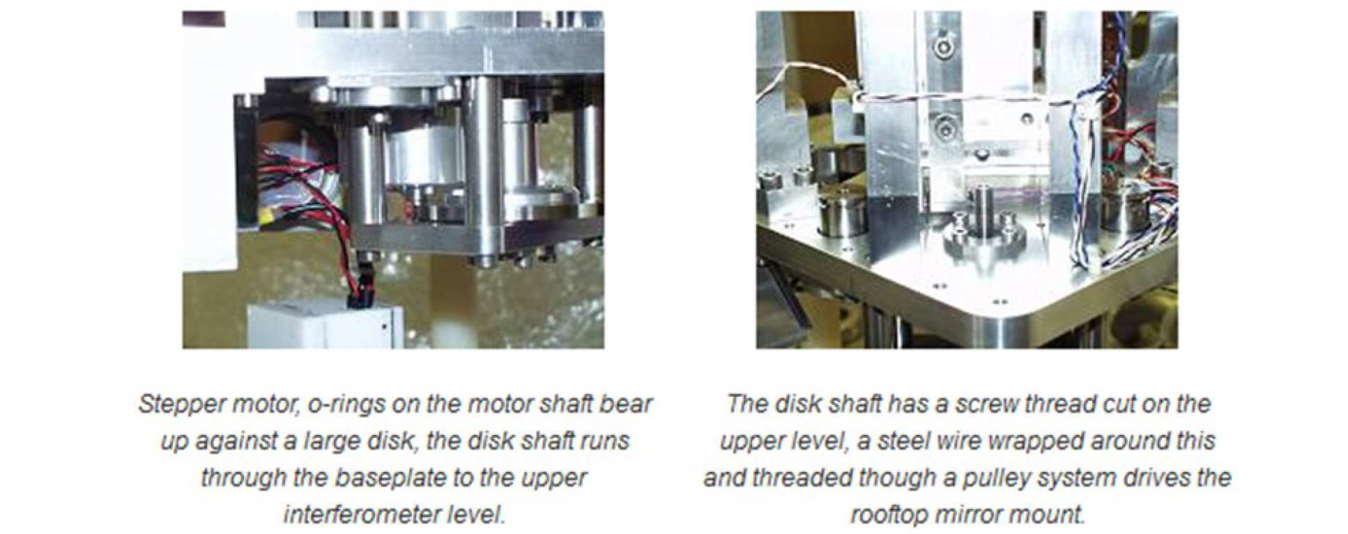
The up-welling and down-welling beams are combined via an input polariser (centre component on the left), and directed to the main interferometer where beam division is accomplished via a second polariser (situated to the right and at 90 degrees to the combiner), the polarising properties of the splitter are at 45 degrees to the combiner, this gives the 50/50 split. Both arms of the interferometer are scanned differentially, and a retro-reflecting roof prism (X-shaped monolithic block) is used in order to gear up the mechanical motion by a factor of four. The scan mechanism, based upon a micro-stepping motor and gearing system, takes an interferogram every 2 seconds, with a 0.5 second turn around time. The micro-stepper will move the motor 500,000 steps for a single scan.
 The output beam is directed towards the cryostat and eventually analysed by a third polariser to obtain complementary fringe outputs which may be processed to give the differential spectrum directly (i.e. the net radiation flow up or down as a function of wavenumber).
A laser mounted on the underside of the baseplate is used for sampling purposes. A mirror in the laser mount directs the beam though a beam expander to the interferometer level where it takes an off-set path (off-set relative to the infrared signal) though the interferometer. A laserfringe detector is mounted on this upper level.
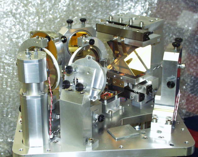
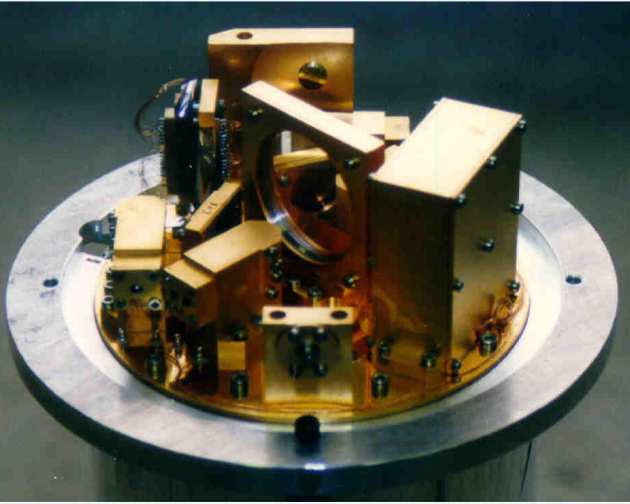 Inverted view of the 5-inch diameter cryogenic optical system: the input beam arrives from the front and strikes a small mirror in a dished mount seen directly ahead. The analyser straddles the centre of the plate (in a large circular mount), and two detector blocks are visible at the lower left separated by an inclined dichroic filter. The large box to the right houses the preamplifiers.
The detectors are highly-sensitive photoconductors (Si:Sb for the shortwave channels, Ge:Ga for the longwave channels); their band-gaps are so low that they must operate at liquid helium temperature (4 K), and the associated optics must be designed so as to minimise the interception of stray radiation whilst maximising the capture of the wanted signal. Several strategems are employed to these ends in a novel design:
- The system defines a field of view of +/- 0.8 degrees (consistent with the required resolution) and rejects energy arriving outside this angle.
- The aperture of the system is defined using a virtual cold-stop (Lyot stop) positioned in the centre of the interferometer. Any radiation arriving from the surrounding mounts is also rejected.
- Two stages of filtration are provided to prevent the ingress of shortwave radiation (a cut-off at about 700 cm-1 is employed currently)
- Each detector is placed in a small integrating cavity which is fed by a combination of a hyperbolic non-imaging concentrator and an off-axis paraboloidal mirror. This gives light capture whilst being more compact and efficient than the more usual compound parabolic concentrator.
In addition to these functions, a polarisation analyser is provided to decode the interference signals arriving from the main interferometer, and dichroic filters are employed to split the light into the two spectral bands required for the detectors. Since the signal currents are quite weak, they are passed through cooled load resistors and transimpedence amplifiers located on the optical assembly before being fed out to external preamplifiers. It was decided to employ photoconductive detectors rather than bolometric units because they offer improved sensitivity (lower noise) and greater speed (operation up to 10 kHz is possible).
The optics and detector components are assembled on a very crowded 5-inch diameter copper disk (gold plated for low emissivity), and surrounded by a radiation shield. This unit is attached to a tank of liquid helium which is in turn surrounded by a liquid nitrogen cooled radiation shield and a vacuum enclosure. The cryogen hold time is approximately 12 hours. Ribbon cables manufactured from 42-gauge constantan wire carry the signals to the preamplifiers and digitisers which are housed in an enclosure bolted to the cryostat casing.
The detectors are provided with bias voltage by the preamplifiers, and the signals are passed to DC-coupled differential amplifiers prior to digitisation. Two low-cost stereo sigma-delta analogue-to-digital converters are employed for this task; they have high resolution (20 bits) and linearity, and the invaluable feature of a built-in (digital) anti-aliasing filter which would otherwise be extremely difficult to implement. These features make the ADCs ideally suited to Fourier transform spectroscopy. The interferogram signals occupy a bandwidth up to about 4 kHz, but sampling is undertaken at a constant 20 kHz rate for extra precision. Digital data are transmitted to a special interface in serial form at the rate of 80,000 samples per second.
The entire sampling system is locked to a high speed master clock signal at 40 MHz (25 ns period); this signal is divided to obtain the sampling clock used by the digitisers, and is also fed to a gated counter-timer circuit. This counter accumulates clock ticks until a laser fringe is detected, at which point the count value is latched and transferred to a memory for later reading by the control computer. The result is a stream of time values indicating when each fringe occurred or, equivalently, those times at which the optical path difference in the interferometer was an integral number of laser wavelengths. These timings establish a uniform spatial sampling grid, and also act as valuable diagnostics for the quality of the scan drive. This system in novel, and this is the first time it has been implemented in a flight instrument.
The four channels of digitised data and the laser fringe timings are collected in two buffer memories and read out by the integrated control computer using special real-time extensions to its operating system. The program is written in the C language, and the data are input via a redundant hard disk interface for speed and economy. A total volume of about 570 kBytes is obtained for each 2-second scan, and the raw data are saved on two SCSI hard disks (3.2 GByte capacity) in binary form. Data are acquired on both "forward" and "reverse" scans but the resultant files are stored on separate disks for security. Although the computer is "only" a 486-based PC, its operating system (LINUX) is so efficient that it has plenty of spare capacity, and can support full network connections whilst it is taking data. The raw data are stored after some re-packaging and checking, but are not processed by the control computer primarily for reasons of storage space.
Post processing is required to convert the uniform-in-time sampled data streams from the digitisers into uniform-in-space sampled interferograms before the spectra can be calculated. This conversion is carried out using interpolation by pre-computer FIR filters, according to a scheme originated by J. Brault4. The process is very fast and yields high-quality interferograms which have been corrected for scan drive non-uniformities or vibrations to within half a clock tick (i.e. +/- 12.5 ns). This precision is equivalent to a spatial movement of the mirror block of about 1.6 Å. It is the remaining uncertainty which limits the dynamic range of the system in the spectral domain to about 1 part in 100000. An extensive study was carried out into the interpolation technique and the effects of differing amounts of vibration on the spectra as part of the design process, and a considerable amount of experience has been gained as a result.
In addition to the main sampling system, the control computer monitors and controls the temperatures of the on-board black bodies, and it can access an array of temperature sensors placed around the instrument. The computer manages the target selection and scanning sequence using special-purpose motor controllers. The system is designed to be completely autonomous, requiring minimal operator intervention; it is hoped that in consequence it will be compatible with a wide range of platforms.The TAFTS instrument has been designed entirely by the IC team (mechanics, optics, electronics and software), with invaluable advice on the cryostat from QWM along with the supply of the photoconductor detector crystals, polarisors and dichroics.