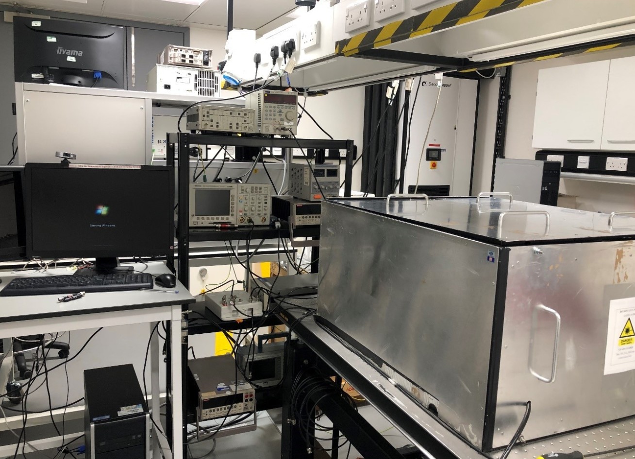
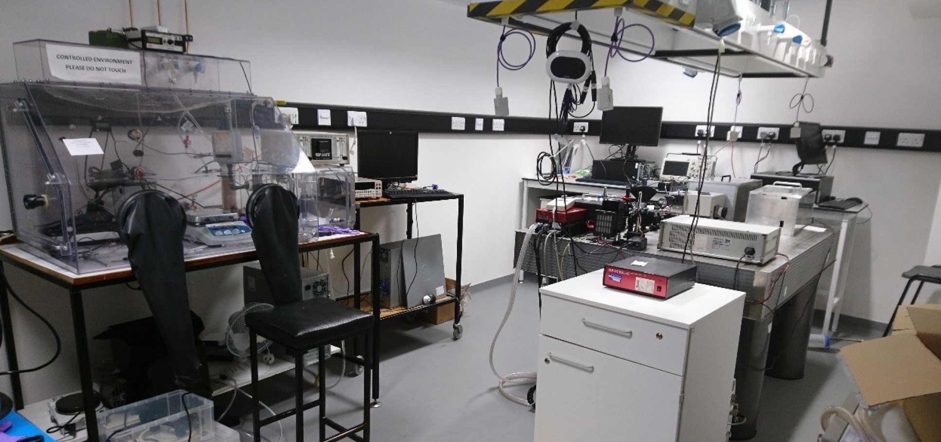
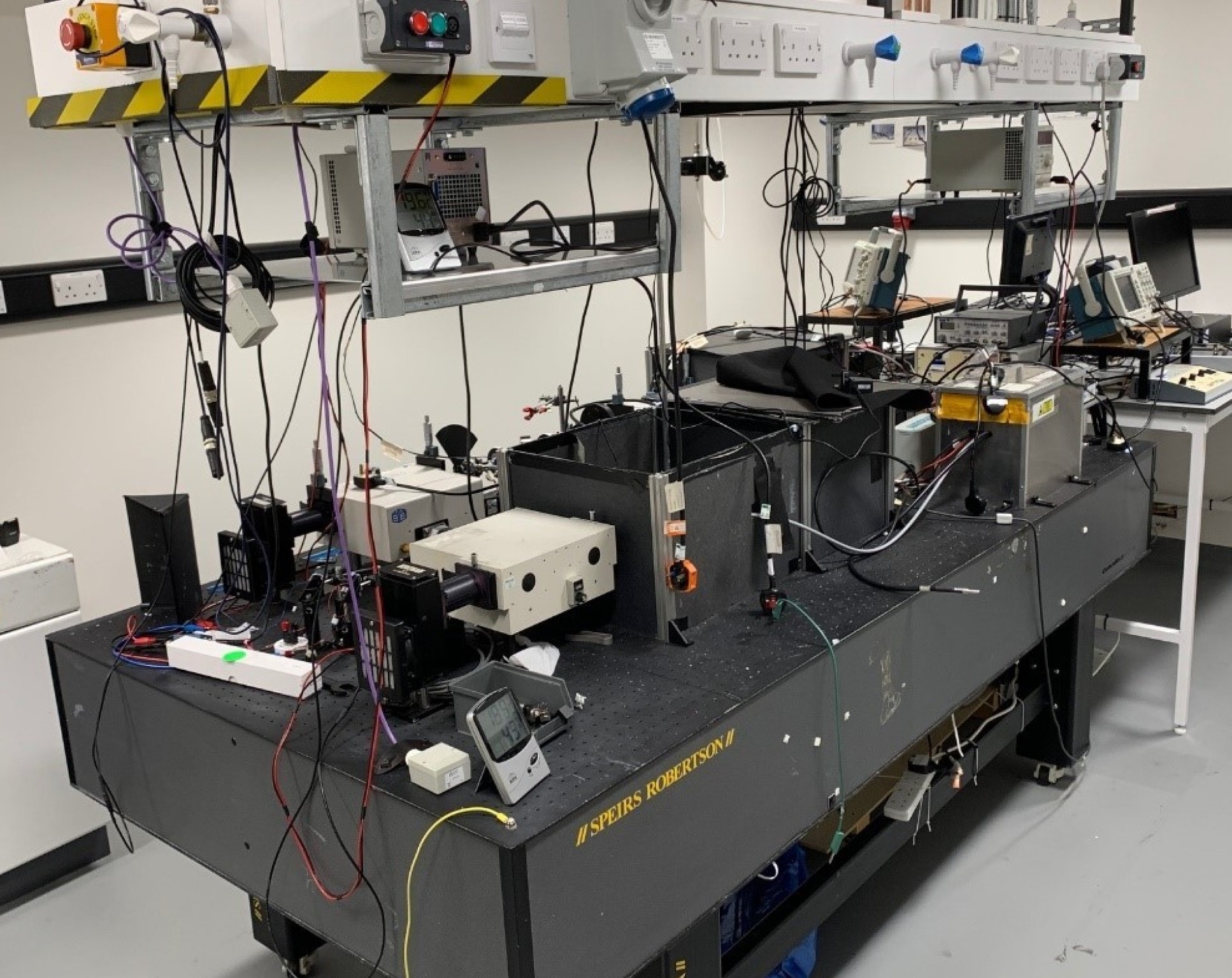
Our spectroscopy facilities are located in the Laser suite B25 in the basement of MSRH building, White City Campus.
TAS system
TAS is a time-resolved pump-probe technique which was originally developed by Lord Porter to study the behaviour of short-lived radical species. Typically, a short light pulse (pump) is used to excite the material in question, and the resulting change in the optical density of the material due to the photogenerated species (i.e. photogenerated holes and electrons) are monitored using a second light beam (probe) which is time-delayed with respect to the pump.
DR-TAS
Location: B25A
On this system, ‘pump-probe’ measurements that monitor transient photogenerated species can be conducted on the mm-s timescale in diffuse reflectance or transmission mode. Here, the third harmonic of a Nd:YAG laser (OPOTEK Inc., Opolette 355 laser system, 6 ns pulse width) provides 355 nm excitation. Alternatively, the Opolette can be tuned to a range of excitation wavelengths. A liquid light guide with a 0.5 cm diameter guides the laser pulse to the sample. Continuous probe light illumination of the sample is achieved using a 100 W Bentham IL1 quartz halogen lamp, followed by an IR filter (H2O, 5 cm path length) to prevent sample heating by the lamp. The set-up of mirrors is adjusted for diffuse reflectance and transmission modes accordingly, to direct the reflected/transmitted light from the sample, through long pass filters (Thorlabs) and a monochromator (Oriel 4 Cornerstone 130), prior to being focused onto a choice of a visible or IR Silicon photodiode detector (Hamamatsu S3071). The output from the photodiode on the mm-ms timescales is electronically amplified (Costronics) and recorded on the oscillopscope (Tektronics TDS 2012B), whilst the DAQ card (National Instruments, NI USB-6211) records data on ms-s timescales. The percent change in absorbance before and after laser excitation is calculated using home-built LabView software.

Bias can be applied to samples during measurements using an Autolab potentiostat. Transient photocurrent (TPC) measurements can be carried out by modifying the set-up, such that the oscilloscope measures the photocurrent resulting from the laser pulse as a function of time. Photoinduced absorption spectroscopy (PIAS) can be conducted using the system, as detailed in the SF TAS/PIAS description.
TPV-rig
Location: B25B
Transient optoelectronic characterisation (CE/TPV) rig
Many optoelectronic techniques have been applied to understand the transport properties and recombination dynamics in BHJ solar cells. In our lab, we employ transient optoelectronic techniques with a combination of charge extraction (CE) and transient photovoltage/photocurrent (TPV/TPC) to allow experimental quantification of carrier density, lifetime and effective mobility under different charge carrier density or field during operation. The schematic diagram of the TPV- rig measurement is shown below.

The basic set up of the transient optoelectronic rig employed in this lab has an oscilloscope (Tektronix TDS 3032B) to record the transient signal. A ring of 12 Luxeon Star/O (LXHL-NWE8) white LEDs to supply background light intensities. The laser sources is a Continuum Minilite Nd:YAG to apply small laser perturbation, the wavelength used in this thesis is 532 nm. The bias supply is a Keithley 2400 source meter to provide different voltage condition to the device. All of these are controlled via the computer with in-house software written in Wavemetrics IGOR Pro software.
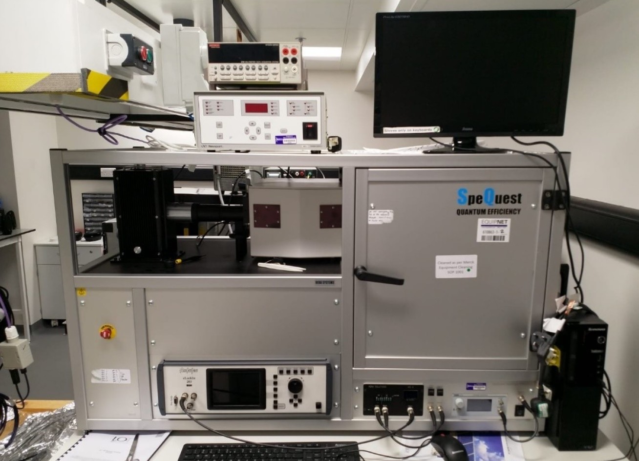
External quantum efficiency measurement unit
Location: B25B
The PVE300 is a turn-key solution for the determination of solar cell spectral response/EQE (IPCE) and IQE.
PV-TAS
Location: B25D
The schematic illustration of the sysetm is show below.
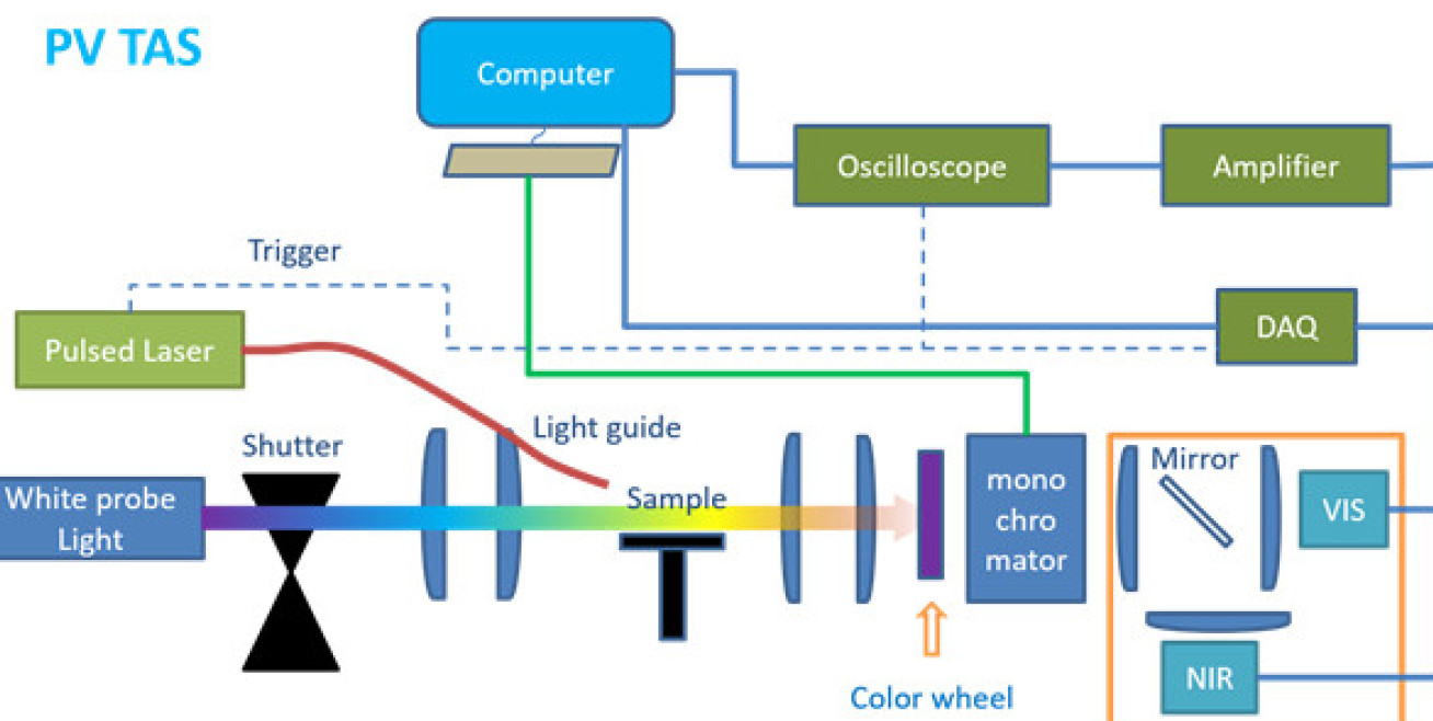 Schematic illustration of the PV- TAS from microsecond- second measurements pump-probe measurements
Transient absorption spectroscopy (TAS) measurements on the microsecond – second timescale were carried out on a home-built configuration consisting of a pulsed Nd:YAG laser (OPOTEK Inc., Opolette 355 laser system, 7 ns pulse width) at 355 nm. The light source used for the probe beam is a 100 W tungsten lamp coupled to a monochromator. The probe beam is first passed through a shutter, and then through longpass filters (color wheel) after samples to filter the scattered laser light, then through a monochromator set to the same wavelength as the probe beam. To detect the transmitted photons, two Si-photodiode are employed with one for visible and another for near IR. The obtained data are processed through an amplifier (Costronics) and subsequently recorded by an oscilloscope for the μs-ms timescale, and the ms-s to second timescale data were recorded with a DAQ card. The system and data acquisition are controlled by a home-programmed Labview software
SF-TAS/PIAS
Location: B25F
Our slow (µs – s) timescale pump-probe setups can be modified to perform both transient absorption spectroscopy, as well as pseudo steady state – photo induced absorption spectroscopy. Both systems are described below.
1. Microsecond – second TAS measurements
Schematic illustration of the TAS set-up for microsecond-second pump-probe measurements is shown here.
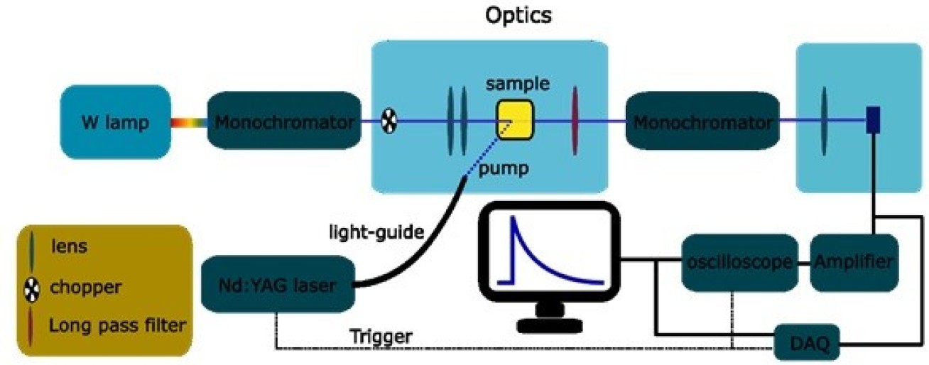 Schematic illustration of the TAS set up for microsecond-second pump-probe measurements
Transient absorption spectroscopy measurements on the microsecond – second timescale were carried out on a home-built configuration consisting of a Nd:YAG laser (OPOTEK Inc., Opolette 355 laser system, 7 ns pulse width) at 355 nm. The light source used for the probe beam is a 100 W Bentham IL1 tungsten lamp coupled to a monochromator (OBB-2001, Photon Technology International). To filter scattered laser light, the probe beam is passed through longpass filters and another monochromator (or bandpass filter) set to the same wavelength as the probe beam. To detect the transmitted photons, a Si-photodiode is employed (Hamamatsu). The obtained data are processed through an amplifier (Costronics) and subsequently recorded by an oscilloscope (Tektronics TDS 2012B) for the μs-ms timescale, and the ms-s timescale data were recorded with a DAQ card (National Instruments, NI USB-6211). The system and data acquisition are controlled by a home-programmed Labview software. Electrical bias can also be applied to the sample using an Autolab potentiostat (PGSTAT 101, Metrohm).
2. Photo-induced absorption spectroscopy (PIAS)
The set up of the SEC-PIAS set up used to monitor the photo-induced optical and the transient photocurrent signal under continuous illumination is illustrated below.
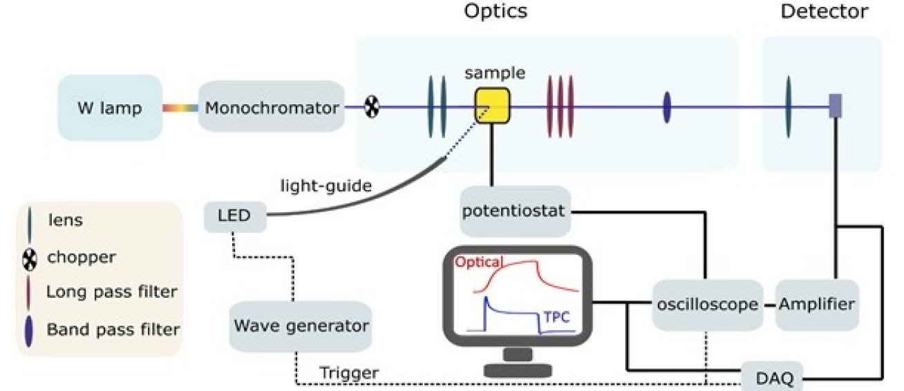 Schematic illustration of the SEC-PIAS set up used to monitor the photo-induced optical and the transient photocurrent signal under continuous illumination
Photo-induced absorption spectroscopy (SEC-PIAS) is a steady-state pump - probe technique employed to study the photo-induced population of accumulated species under continuous illumination ( and at a constant applied potential where processes such as back electron-hole recombination is turned off for spectroelectrochemical PIAS). This technique uses a modified – TAS setup (outlined above), however a continuous LED light source (365 nm) is used instead of a laser pulse, to photogenerate species, which allows the system to reach steady-state. The LED light pulses are generated using a frequency generator to generate 5 V square-wave typically at a frequency of 0.1 Hz, that also triggers the MOSFET (STMicroelectronics), the LED power supply (TTI), the oscilloscope (Tektronics) and the DAQ card (National Instruments). Both the optical changes in the sample (recorded as ΔOD) and the concomitant transient photocurrents (TPC) are recorded simultaneously. The TPC are recorded using the oscilloscope coupled to an Autolab PGSTAT 101 potentiostat (Metrohm).
fs-TAS
Location:B25E
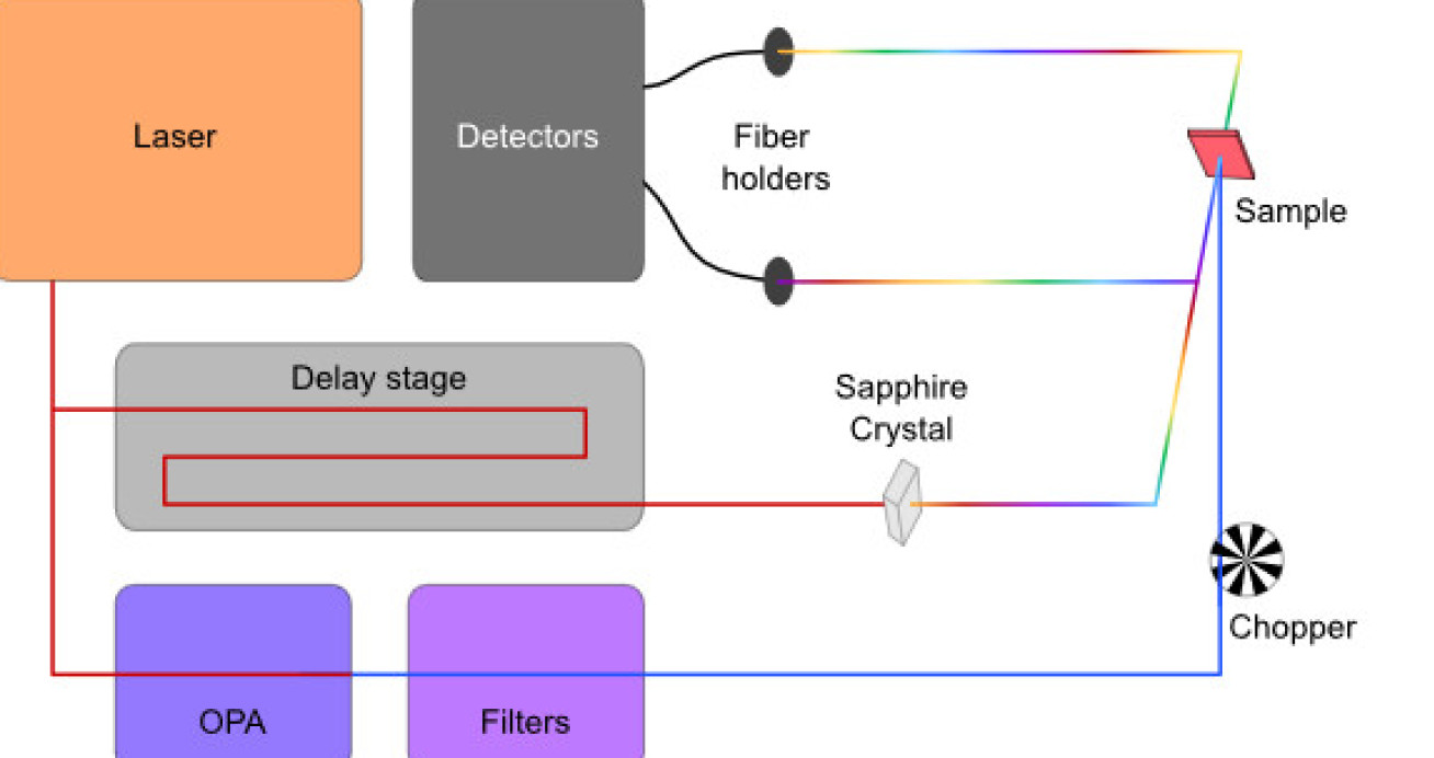
Our ultrafast transient absorption setup uses a regeneratively amplified Ti:sapphire laser (Solstice, Spectra-Physics), which produces 800 nm laser pulses with a width of 92 fs at 1 kHz repetition rate. The transient absorption setup which it drives is commercially available (Helios, Ultrafast Systems), and the entire setup is schematically shown below.
Spectroscopy

Fs-Laser system in Laser Suite B25E

Fs Laser-Solstice Spectra-Physics

Optics of the Fs system
After the Solstice amplifier, each pulse is divided into what will become pump and probe pulse using a semitransparent mirror. The pump pulse is directed through an optical parametric amplifier (TOPAS Prime, Light Conversion) and a frequency mixer (NirUVis, Light Conversion), which allows for tuning of the excitation wavelength from ∼290 nm up to the NIR region. The probe pulse is directed through a delay stage which delays it by an adjustable time period with respect to its corresponding pump pulse, thus defining the time at which the sample is probed. The maximum delay is ultimately defined by the total length of the delay stage, and in this case corresponds to ∼6 ns. After the delay stage, the (at this point still 800nm) probe pulse is focussed into a sapphire crystal, which transforms the monochromatic beam into a white light continuum via self-phase modulation. The resulting continuum allows to probe an entire wavelength range at once: depending on the thickness of the inserted sapphire crystal, either a visible probe continuum (450 – 800 nm) or an NIR probe continuum (850 – 1400 nm) can be generated. The generated continuum pulses are then again divided using a semitransparent mirror, where one of them probes through the sample and the other one serves as a reference to account for fluctuations and improve the signal-to-noise ratio. Each of the two continuum pulses is eventually focussed into a separate multichannel spectrometer (Si or InGaAs sensors) via optical fibres. The continuum pulse that probes through the sample is then spatially overlapped with the pump pulse on the sample. The measurement of the absorbance in the excited state AES and the absorbance in the ground state AGS for the calculation of the absorbance difference ΔA is achieved by blocking every other pump pulse with an optical chopper rotating at 500 Hz.