The overall procedure for magnetometer calibration is the conversion of quantities directly measured by the instrument which are in engineering units and delivered via the spacecraft telemetry, into the physical units of nT. This process also involves the conversion of the three components of the magnetic field vector into a standard orthogonal coordinate system. The instrument model describes this calibration process and the full description can be found, along with definitions of all parameters, in the paper Balogh et al.(2001). The full instrument model contains calibration parameters which are determined both on the ground before launch but also parameters which are determined in-flight.
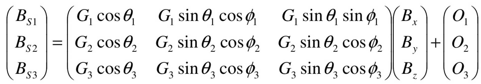
Above: Equation 1
Calibration parameters:
- Elevation angles, θ
- Azimuthal angles, φ
- Gains, G
- Offsets, O
Coordinates:
- Sensor, S
- Orthogonal, x,y,z
After launch, the calibration problem can be represented by equation 1. This equation shows the transformation between a magnetic field vector in the sensor coordinate system and a magnetic field measured in nT in an orthogonal coordinate system. The task of producing calibrated data then comes down to determining the parameters in this calibration equation. There are six angles, three gains and three offsets. There is no single calibration analysis that can be used to calculate all of these parameters. A description of a set of calibration techniques that can be used is in the in-flight calibration section.
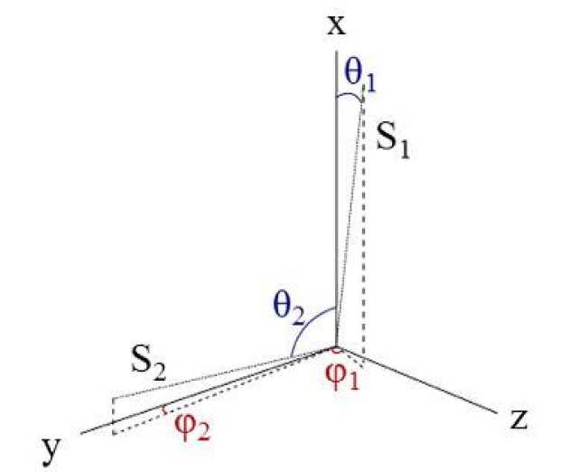 Figure 1: The relation between the orthogonal and sensor coordinate systems. The angles θ and φ for each sensor coordinate is defined in the same way. θ is measured from the z-axis and φ is measured from the y-axis in the y-z plane.