The Penning Trap
Basic principles of the Penning trap
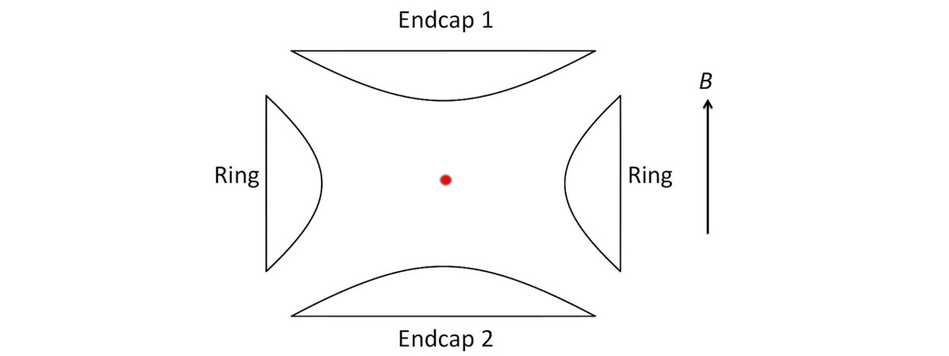
The Penning trap achieves trapping of charged particles using a combination of a static quadrupole electric field and a static uniform magnetic field (for a review see [1]). The electric field is conventionally generated using a set of electrodes as shown in Figure 1. The surfaces of these electrodes are shaped to match the equipotential surfaces of a perfect quadrupole potential given by,

This equation describes a potential well between the end-cap electrodes (called the axial direction), resulting in simple harmonic motion along the z-axis for positively charged particles at the axial frequency νz. However, in the x- and y-directions the potential pushes particles away from the trap centre, towards the ring electrode. In order to counter this, the Penning trap incorporates a uniform magnetic field along the z-axis. In the absence of the electric field, this magnetic field would cause the ions to move in circles in the radial plane at the cyclotron frequency vc=eB/m. The effect of the anti-confining radial electric potential is to modify this single frequency radial motion into a superposition of circular motions at two different frequencies, the modified cyclotron motion (at ν’c) and a lower frequency magnetron motion (at νm).
Oscillation frequencies in the Penning trap
If the two endcap electrodes have a separation of 2z0 and the ring has an internal diameter of 2r0, the axial oscillation frequency of a single ion is given by

where V is the applied potential between endcaps and ring, and e and m are the charge and mass of the ion respectively.
The magnetron and modified cyclotron frequencies are given by:

where the unperturbed cyclotron frequency is given by vc = eB/m. Here, B is the magnetic field strength.
If more than one ion is trapped, these equations describe the oscillation frequencies of the centre of mass (COM), and there are additional degrees of freedom corresponding to internal modes of the cloud of ions, i.e. the relative motion of the ions. In particular, in equilibrium the whole ion cloud generally rotates uniformly at a frequency given by νR, which can take any value between νm and ν’c. This rotation frequency is related to the density of ions in the trap through the equation

See Ref. [1] for more details. For a small number of ions that have formed an ion Coulomb crystal, there are well-defined modes of oscillation for the internal motion.
The Imperial College Penning trap
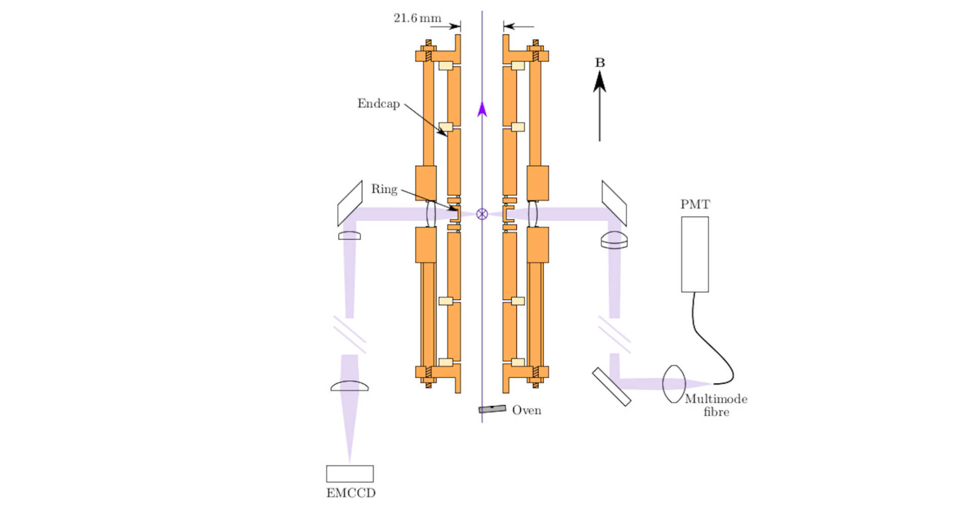
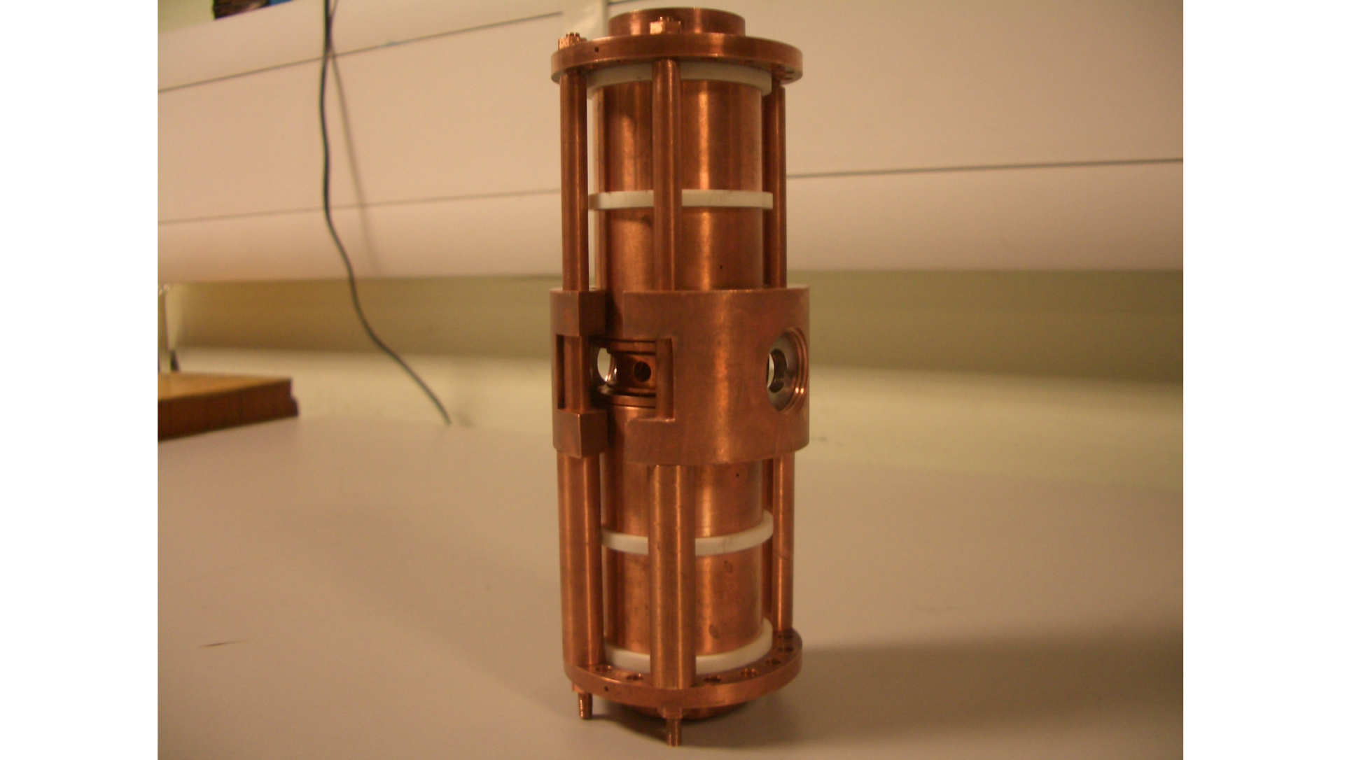
At Imperial College, we have worked with a number of different Penning traps. Our early traps were similar in design to the one shown in Figure 1. These traps operated in the field of a conventional electromagnet. In more recent years we have used a superconducting magnet, which has the advantage of providing a stronger and much more stable magnetic field. A diagram of our current trap is shown in Figure 2 and a photograph of it is shown in Figure 3. In order to fit with the geometry of a superconducting magnet, and to give good optical access to the trap centre (for laser cooling and detection), the electrodes have been opened out to form hollow cylinders. Although the electrode shapes are now very different from the conventional ones, by careful design it is possible to create a trapping potential which is very close to the ideal one near the centre of the trap. In our trap the magnetic field is 1.9 tesla and the internal diameter of the trap is close to 20 mm. The trap is designed to work with calcium ions, for which the oscillation frequencies are typically 100 to 400 kHz for the axial frequency, a few tens of kHz for the magnetron frequency and around 700 kHz for the modified cyclotron frequency.
References
[1] Thompson R C, “Penning traps”. Chapter in: Knoop M, Madsen N, Thompson R C (eds.) Trapped Charged Particles. World Scientific Press, 2016. (Click the link to download chapter)
[2] Bharadia S. Towards Laser Spectroscopy of Highly Charged Ions. 2011. (PhD thesis)
Get in touch
For all your ion trapping needs
004/006 Huxley Building,
Imperial College London,
London
SW7 2AZ

