|
|
|
|
|
|
|
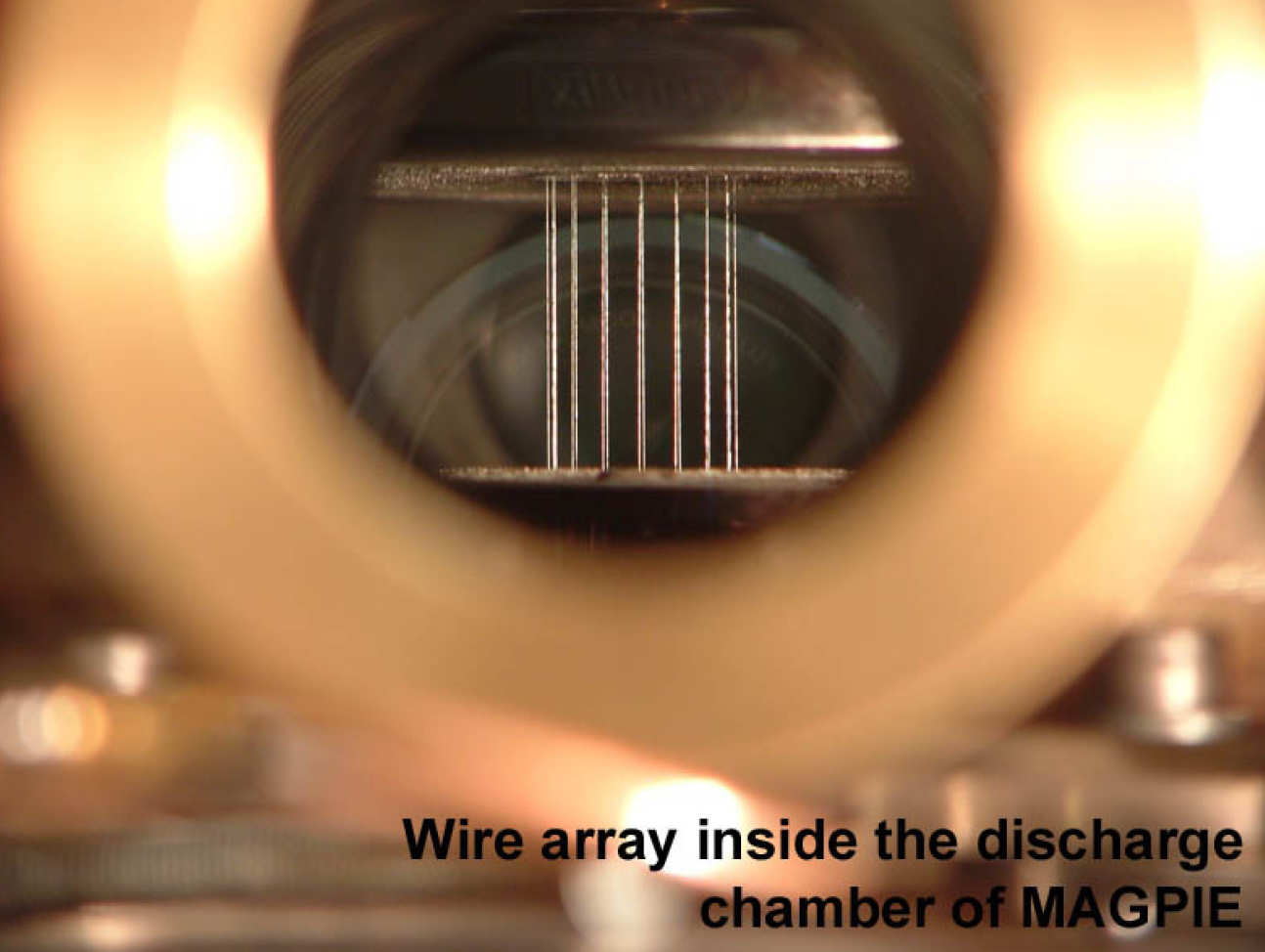
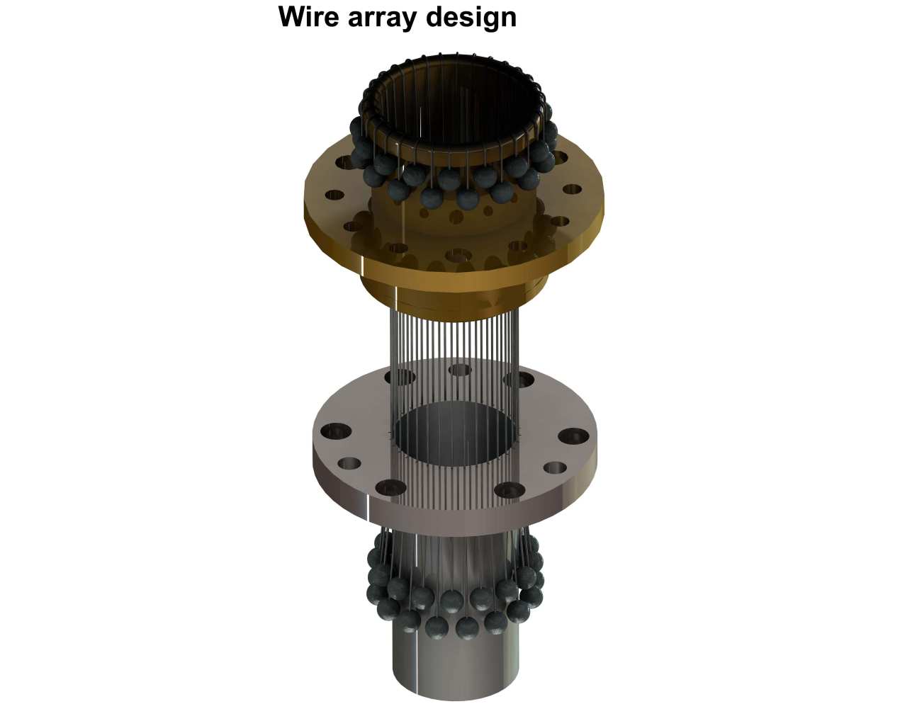
---Copy--tojpeg_1455548653224_x2.jpg) A cylindrical wire array Z-pinch made of 16 wires mounted on custom hardware designed to allow probing of the plasma dynamics through the axis of the array (end-on view). A cylindrical wire array Z-pinch made of 16 wires mounted on custom hardware designed to allow probing of the plasma dynamics through the axis of the array (end-on view).
|
|
|
|
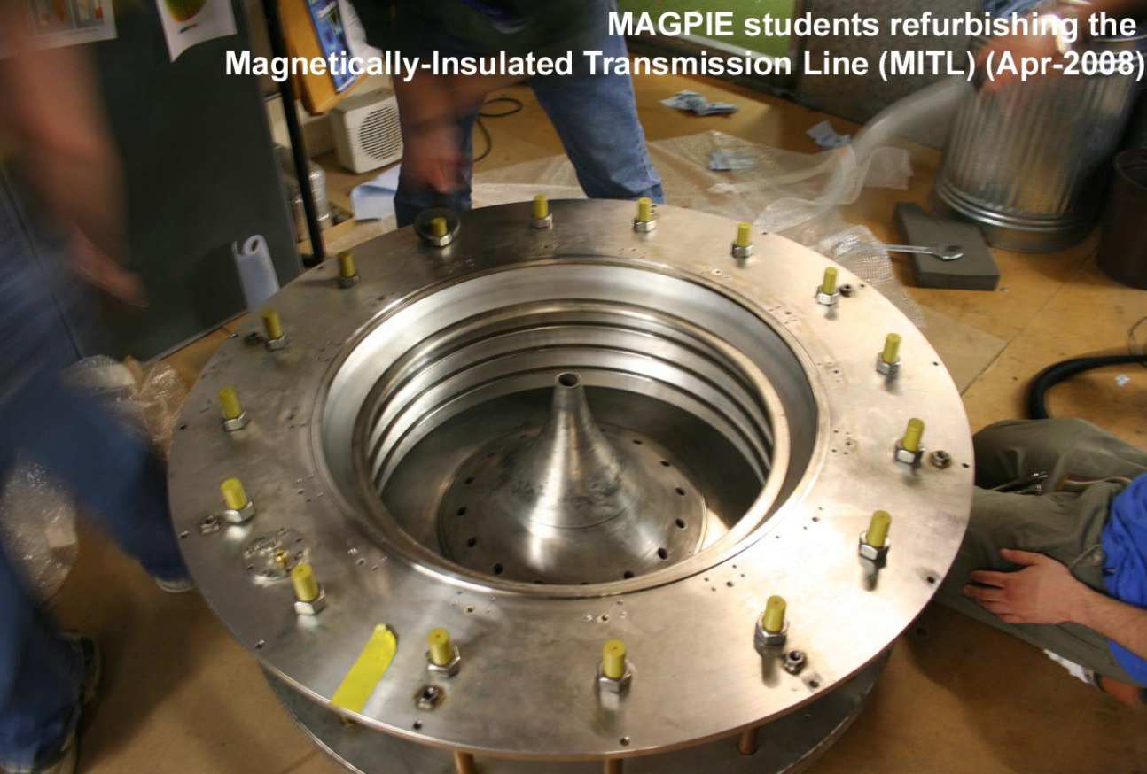
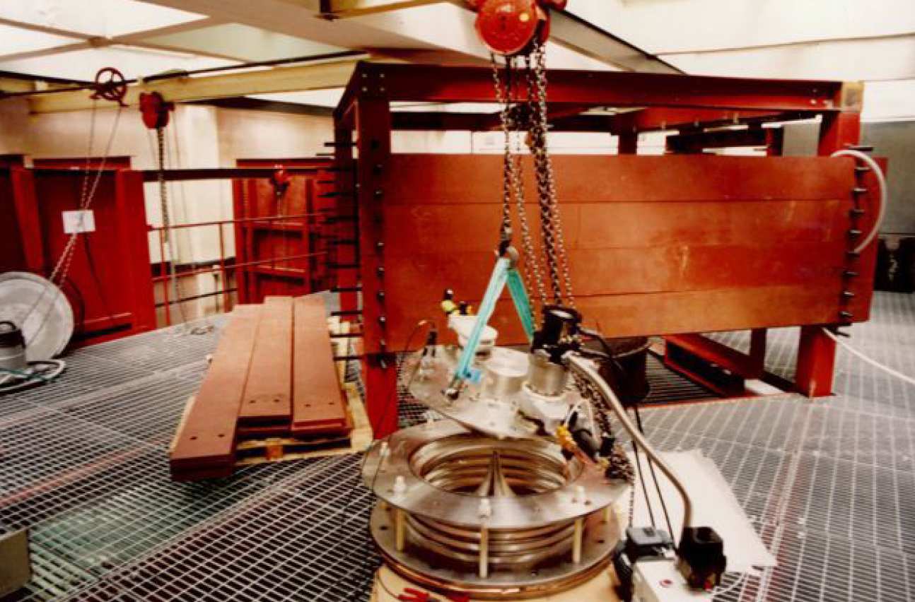
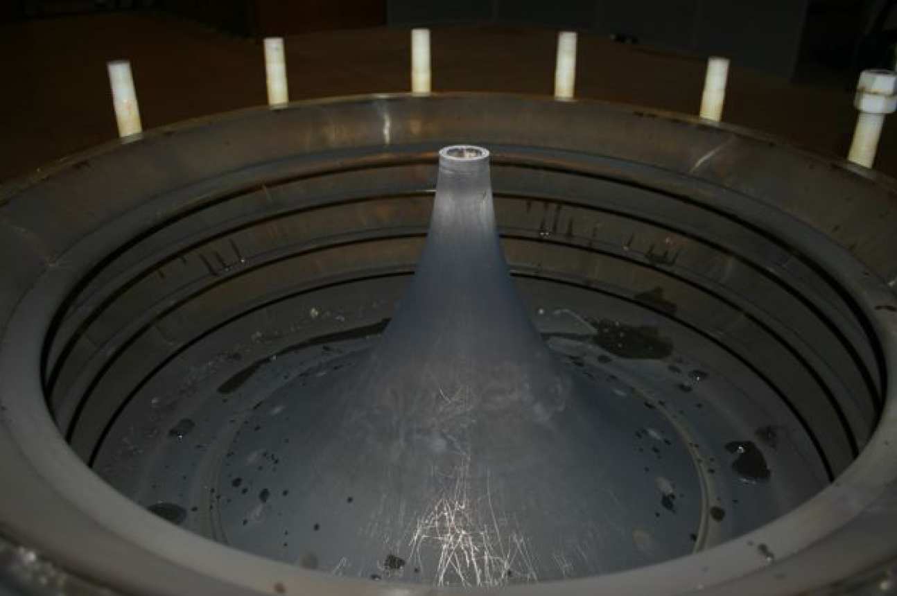 Refurbishment of MAGPIE's magnetically-insulated transmission line (MITL, the conical piece shown in the centre) and the diode stack, a series of insulator rings surrounding the MITL. Refurbishment of MAGPIE's magnetically-insulated transmission line (MITL, the conical piece shown in the centre) and the diode stack, a series of insulator rings surrounding the MITL.
|
|
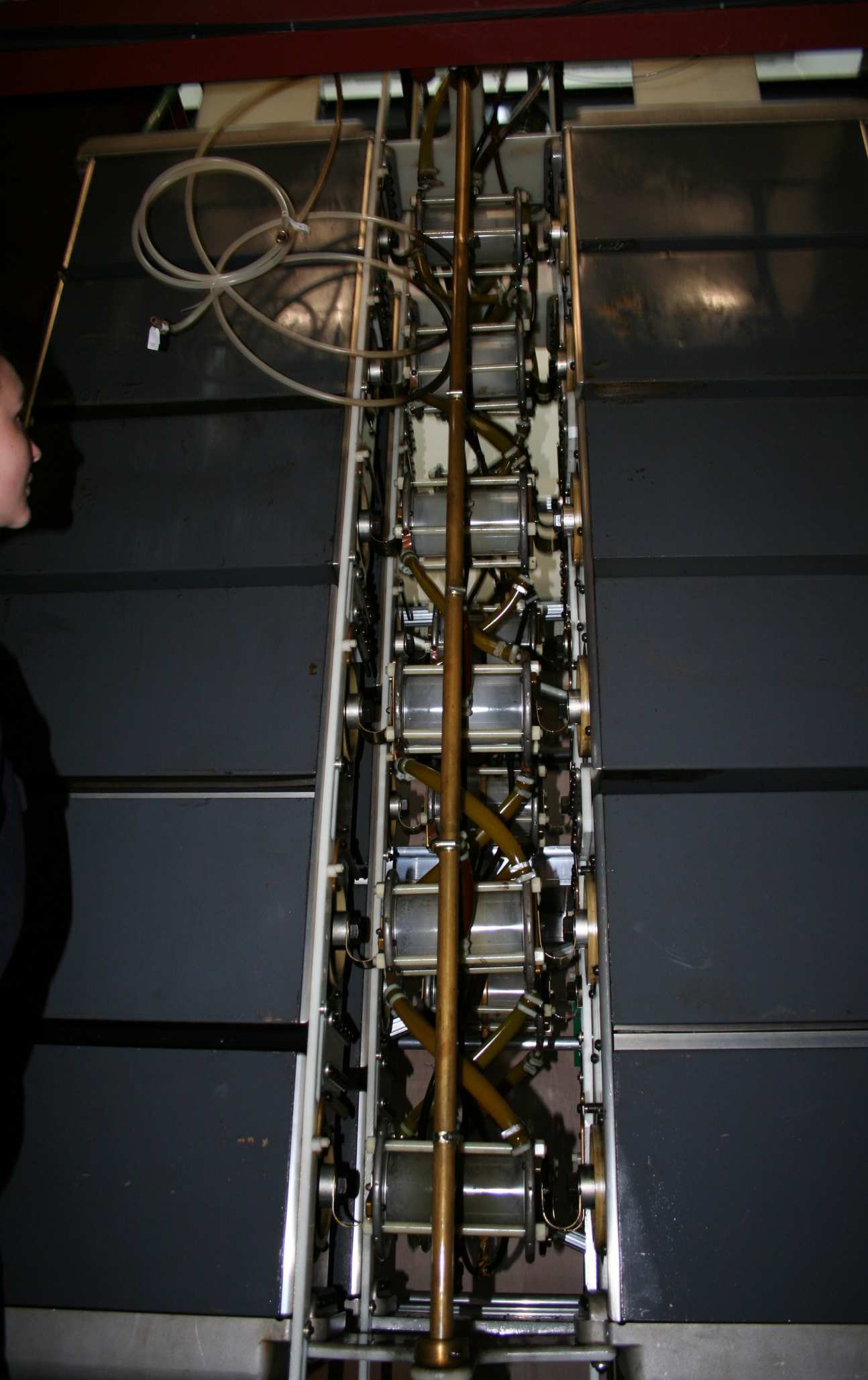
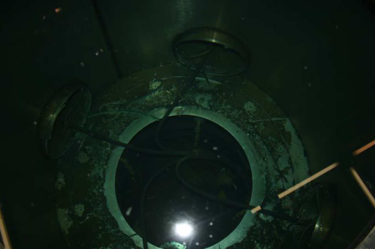 View of the water-filled vertical transmission line. View of the water-filled vertical transmission line.
|
|
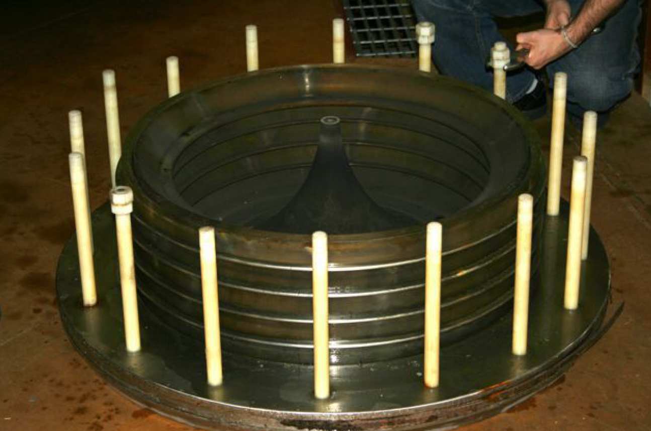 Refurbishment of MAGPIE's magnetically-insulated transmission line (MITL, the conical piece shown in the centre) and the diode stack, a series of insulator rings surrounding the MITL. Refurbishment of MAGPIE's magnetically-insulated transmission line (MITL, the conical piece shown in the centre) and the diode stack, a series of insulator rings surrounding the MITL.
|
|
|
 View of the water-filled vertical transmission line. View of the water-filled vertical transmission line.
|
|
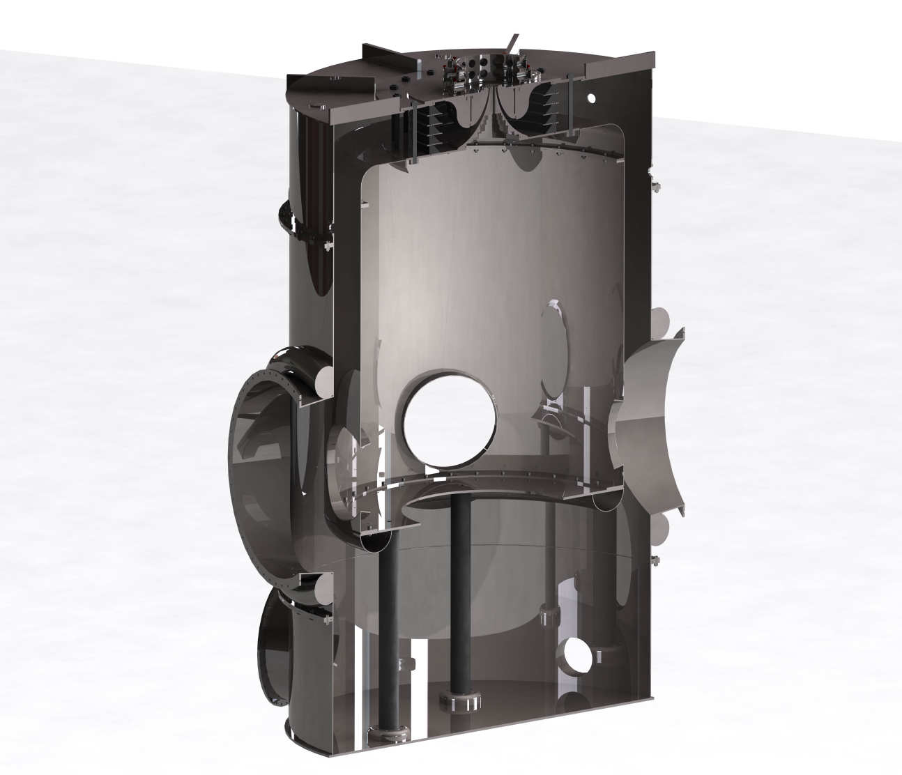
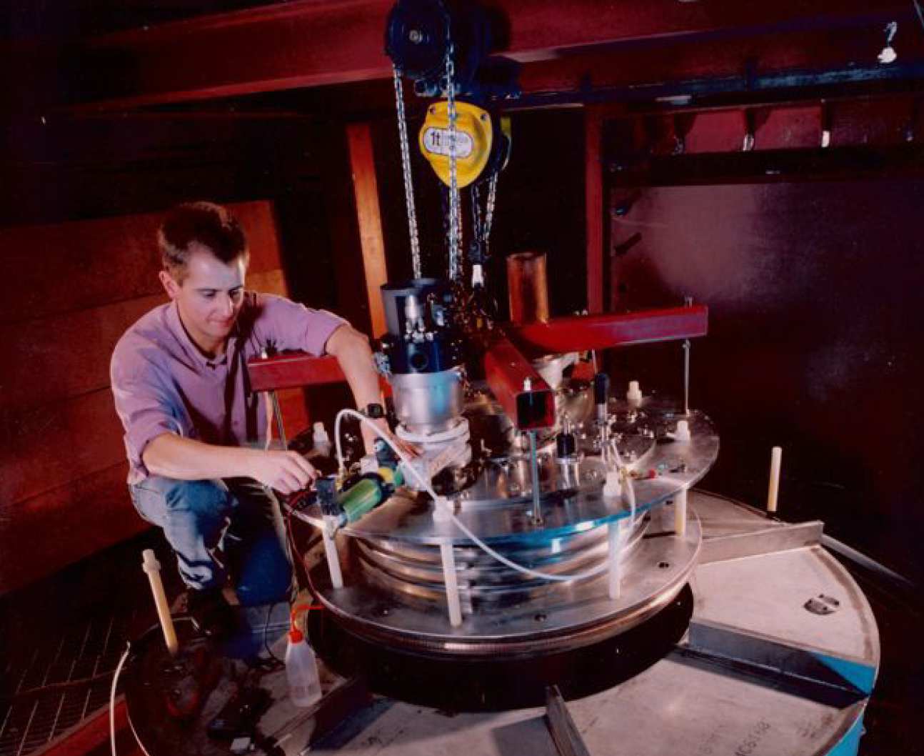
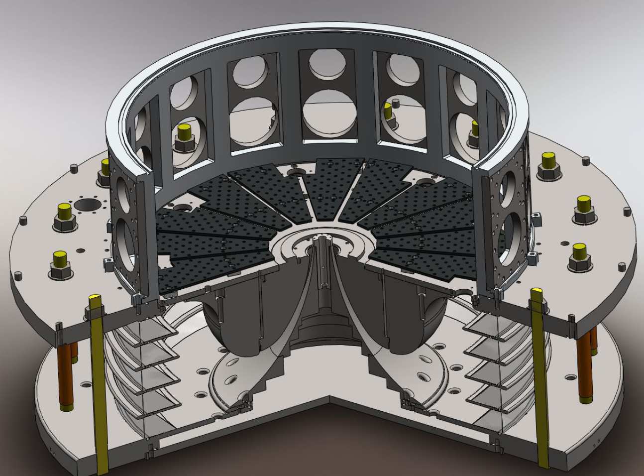 3-D CAD design of MAGPIE's load section. 3-D CAD design of MAGPIE's load section.
|
|
|
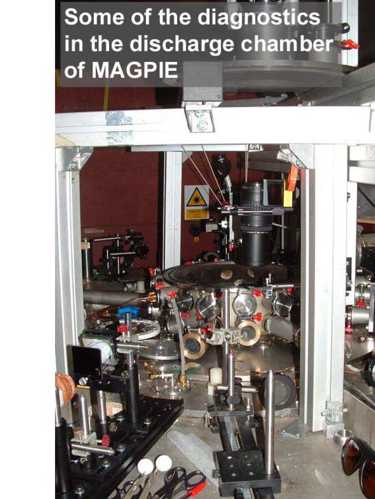
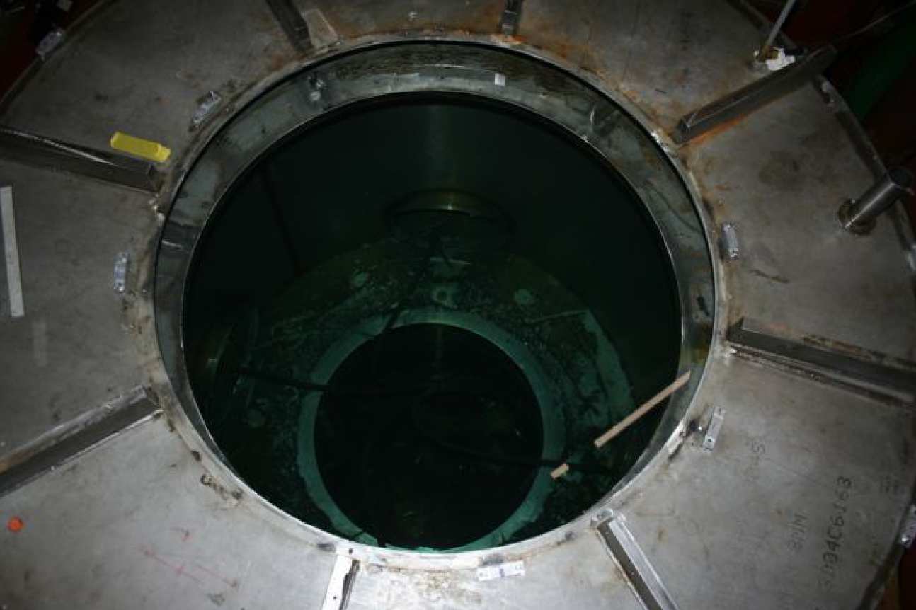
--tojpeg_1455548571214_x2.jpg) MAGPIE's discharge chamber open for shot preparation. MAGPIE's discharge chamber open for shot preparation.
|
|
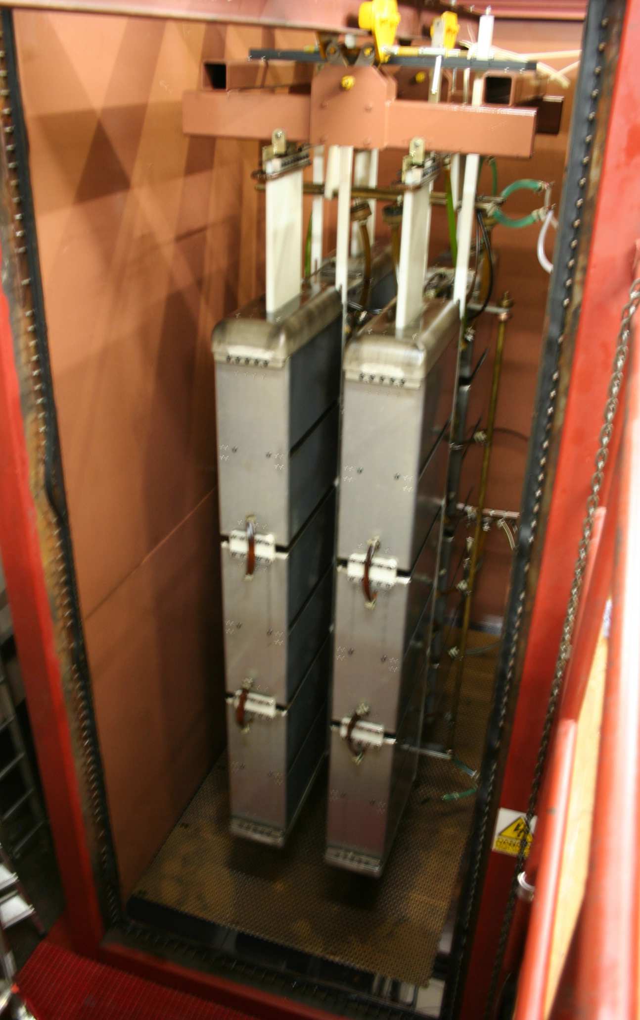
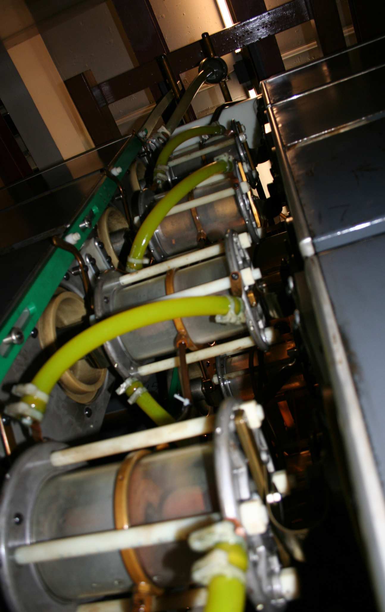 Inside one of MAGPIE's Marx banks, showing 4 high-voltage switches (also known as spark-gaps) each one in between one pair of capactitors. Inside one of MAGPIE's Marx banks, showing 4 high-voltage switches (also known as spark-gaps) each one in between one pair of capactitors.
|
|
|
--tojpeg_1455548723334_x2.jpg) MAGPIE's discharge chamber closed and ready for a shot. MAGPIE's discharge chamber closed and ready for a shot.
|
|
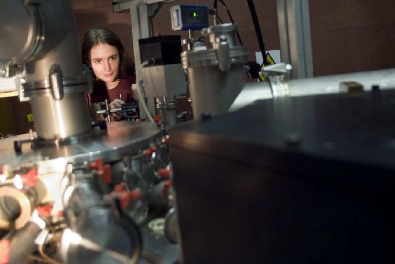
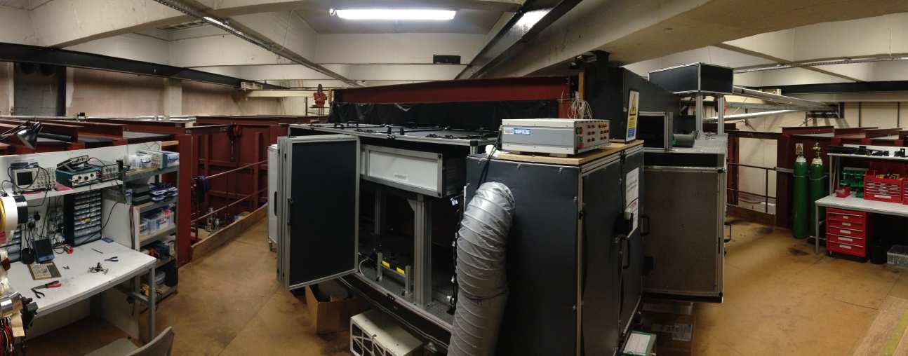
 MAGPIE's top level: one of the areas for diagnostic setup. MAGPIE's top level: one of the areas for diagnostic setup.
|
|
|

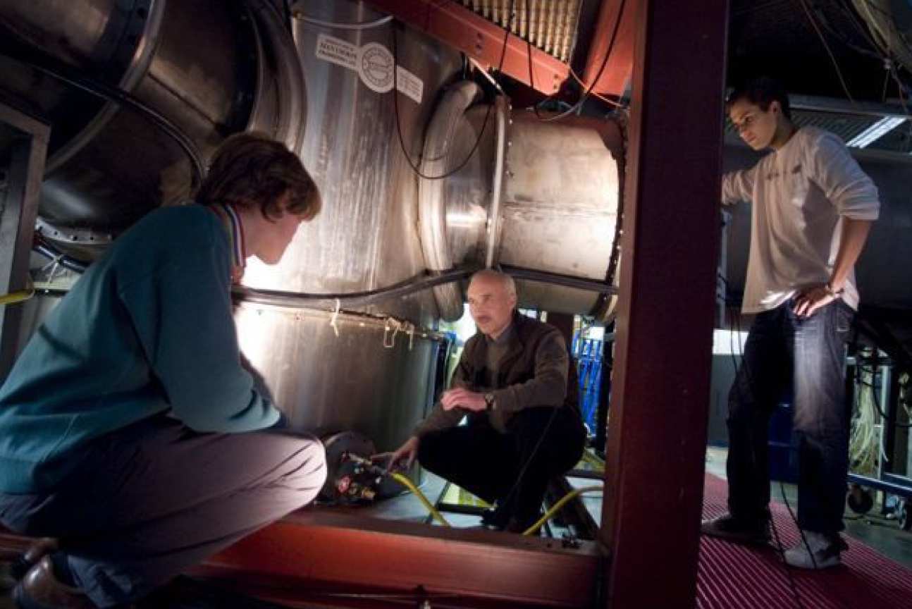
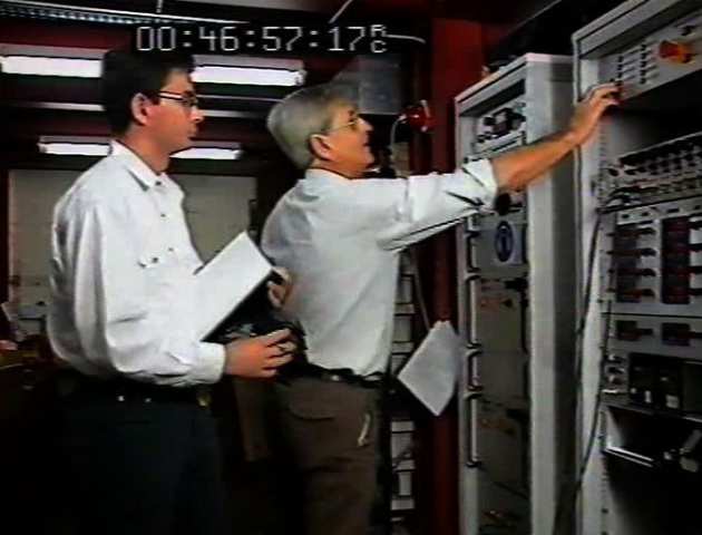
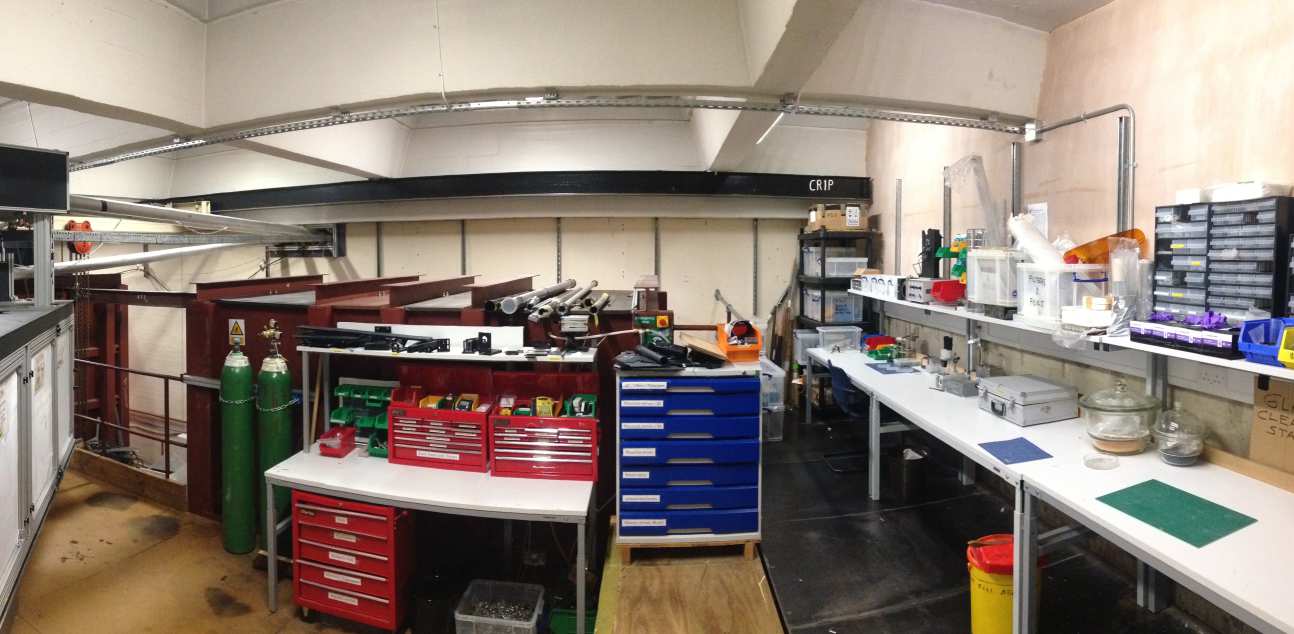
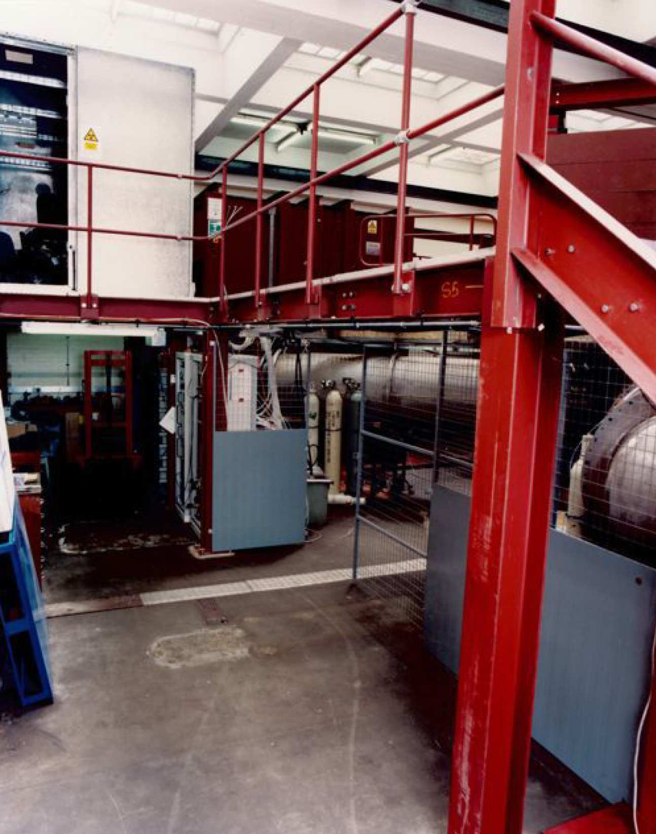
MAGPIE's lower level: Refurbishment area and firing controls.
|
|
|
 MAGPIE's probing laser. MAGPIE's probing laser.
|
|
|
Pulse-forming lines (PFLs)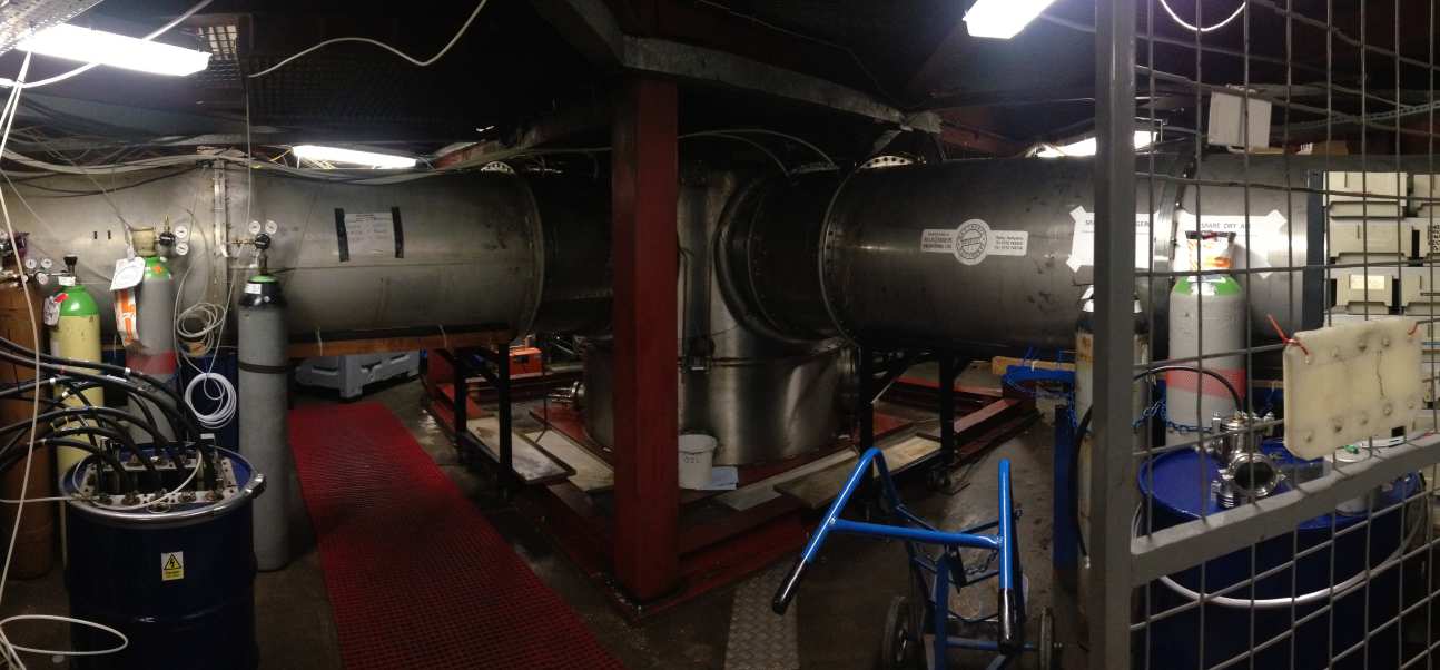
|
|
|
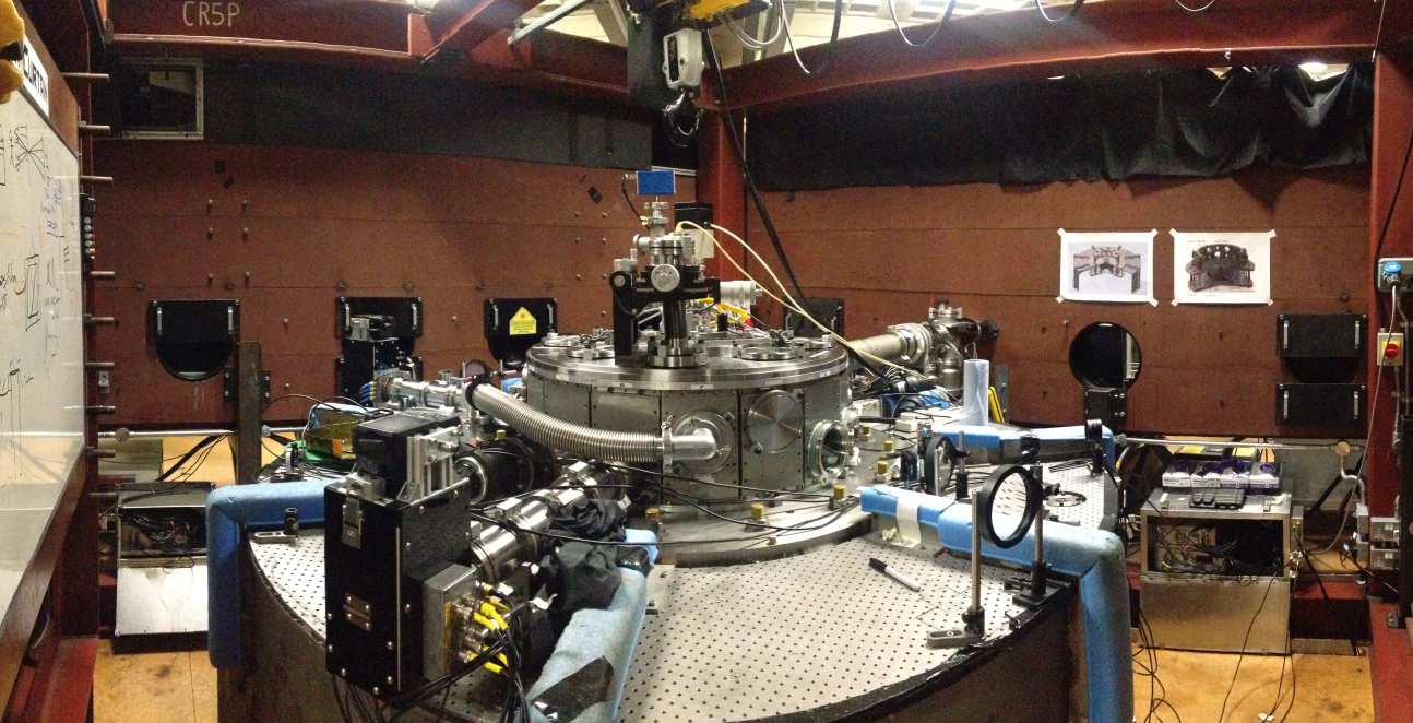 Discharge chamber area. Discharge chamber area.
|
|
|
 Upgrade of one of MAGPIE's Marx capacitor banks. Upgrade of one of MAGPIE's Marx capacitor banks.
|
|
|
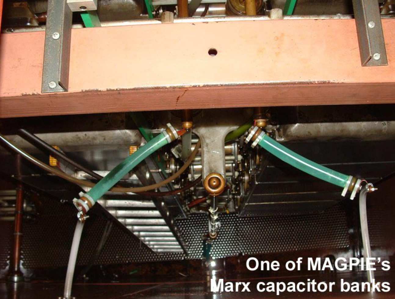
 One of MAGPIE's Marx capacitor banks. One of MAGPIE's Marx capacitor banks.
|
|
|
 3-D CAD render of MAGPIE's vertical transmission line and load section. 3-D CAD render of MAGPIE's vertical transmission line and load section.
|
|
|
|
|
|
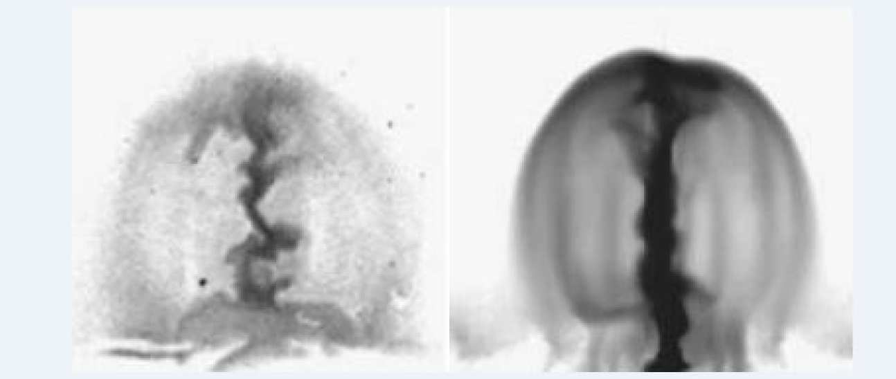 Magnetically-driven jet inside a magnetic bubble from a radial wire array Z-pinch. Experimental results compared to numerical simulations with the MHD code Gorgon. Magnetically-driven jet inside a magnetic bubble from a radial wire array Z-pinch. Experimental results compared to numerical simulations with the MHD code Gorgon.
|
|
 One of MAGPIE's capacitor tanks, also known as Marx banks.
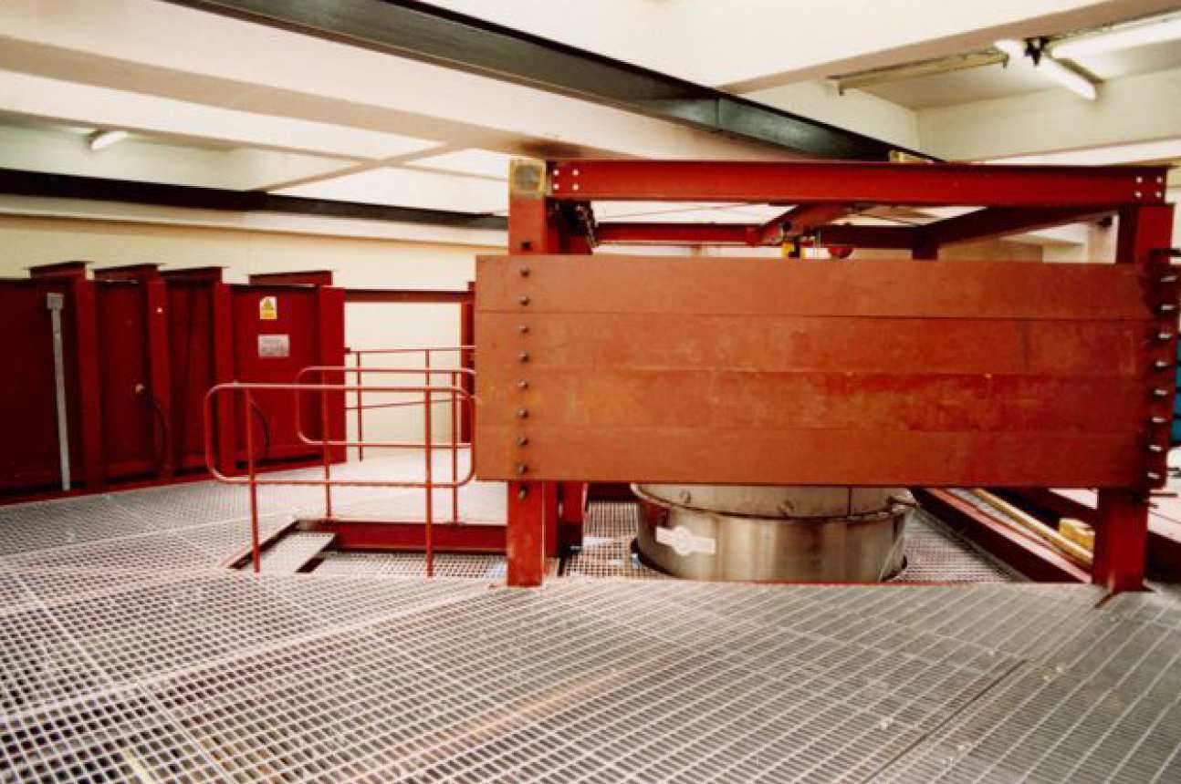 X-ray shielding around MAGPIE's discharge chamber.
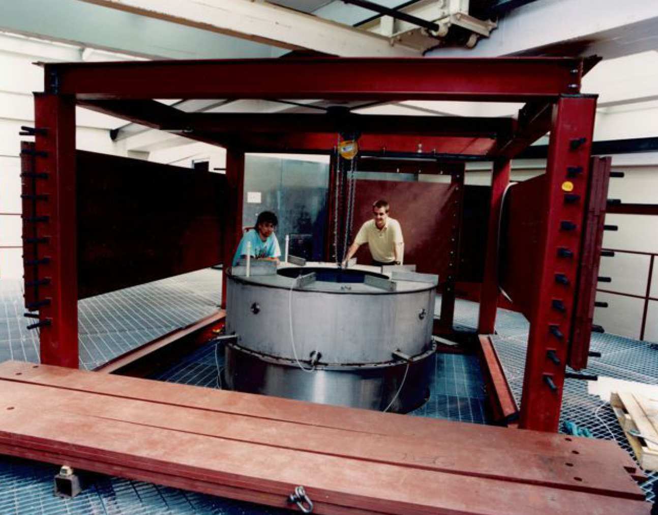 View of the top of MAGPIE's vertical transmission line.
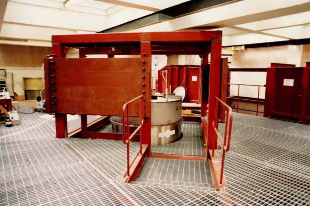 Entrance to MAGPIE's discharge chamber area.
 Installing diagnostics around the vertical transmission line.
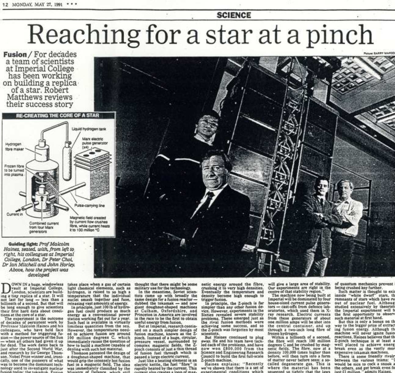 MAGPIE and its researchers featured in the news (27 May 1991). From left to right: Dr Peter Choi, Prof Malcolm Haines, Dr Ian H. Mitchell and John Worley (not Horley!).
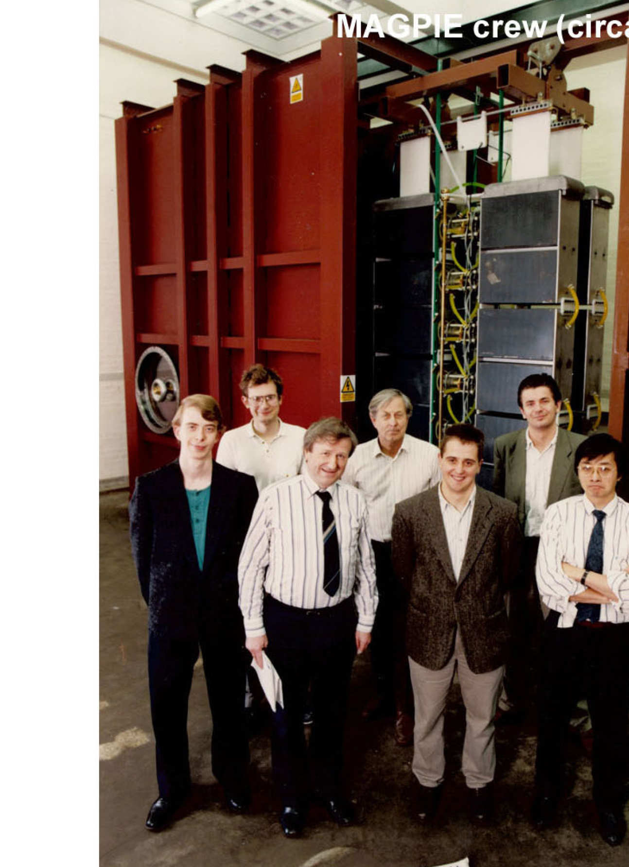
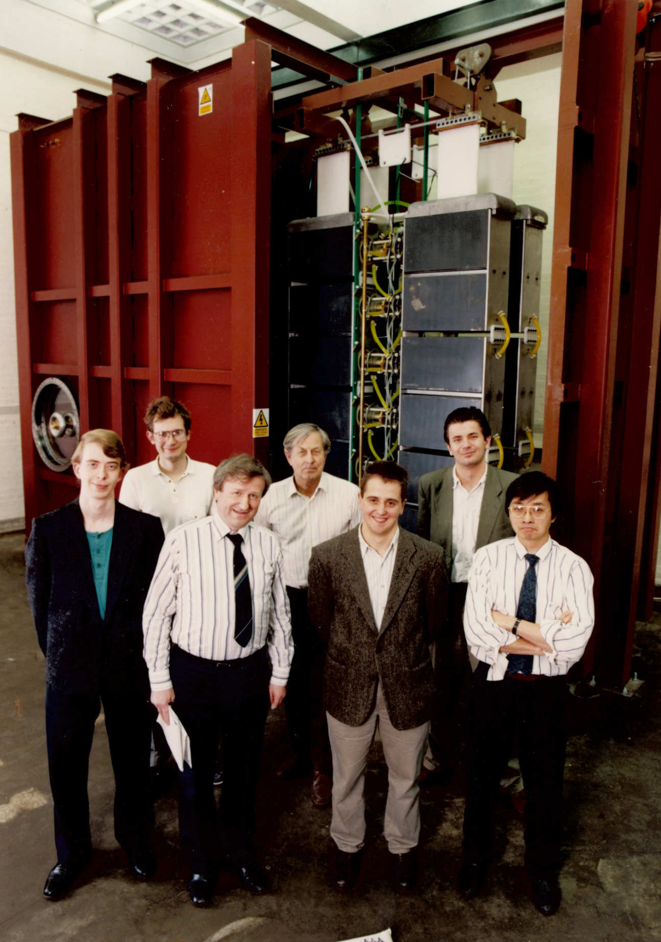 MAGPIE team circa 1994.
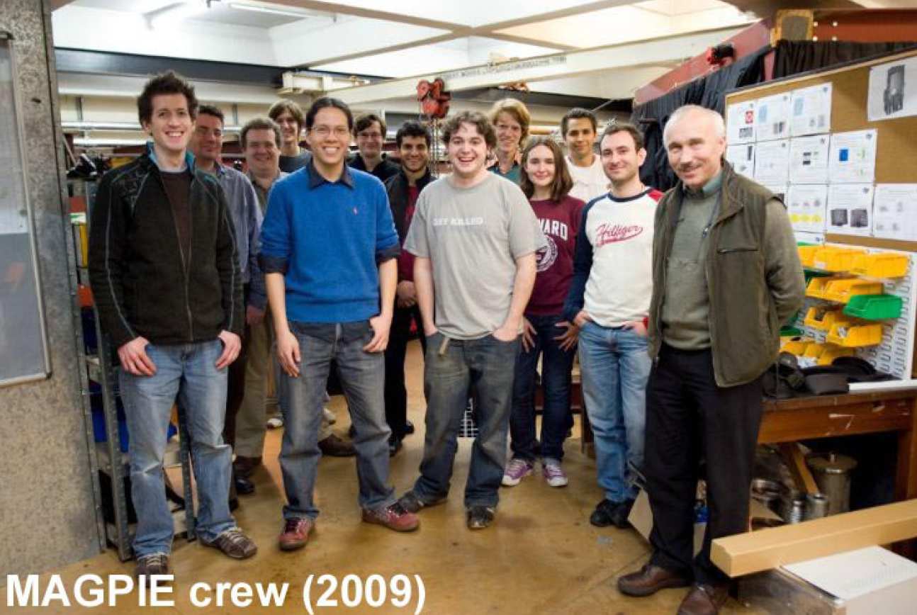
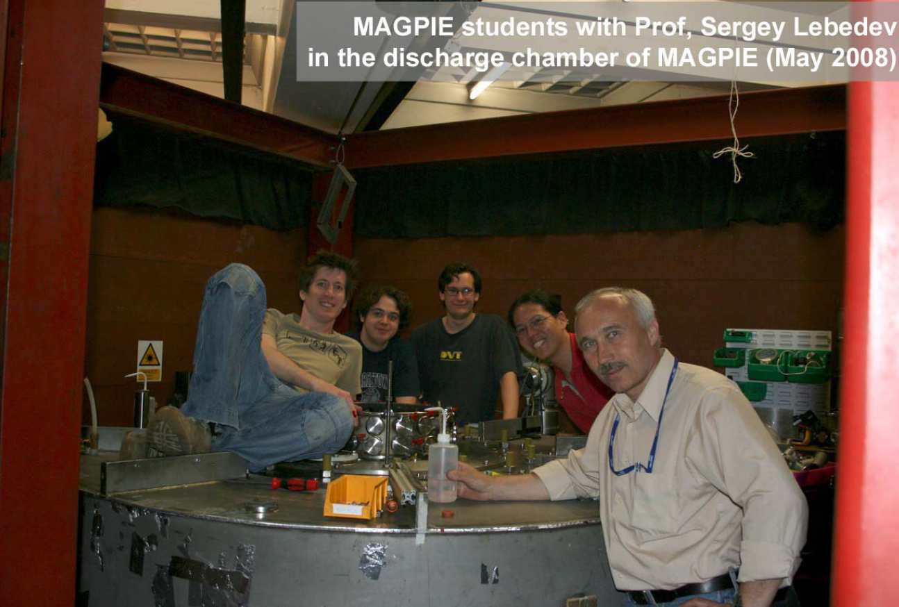
--tojpeg_1455546984494_x2.jpg)
--tojpeg_1455547042227_x2.jpg)