Magnetic Confinement Fusion
Magnetic confinement fusion (MCF), uses deuterium and tritium plasmas heated to temperatures of tens of millions of degrees Celsius. The plasma is confined by powerful magnetic fields, holding it away from material surfaces, using the toroidal geometry of tokamak devices. Current research is strongly linked to the UK’s national fusion research programme at the Culham Centre for Fusion Energy (CCFE), on both the Joint European Torus (JET) and the Mega Amp Spherical Tokamak Upgrade (MAST-U), through both experimental study, the development of theoretical models and simulation. In addition, collaborative projects are ongoing with the DIII-D National Fusion Facility, the largest magnetic fusion research experiment in the USA and EAST in China. All current research has emphasis on topics which are both relevant for fusion energy production and involve interesting, novel plasma physics. In particular, much of the current research fusion research is focussed on key physics issues critical to the success of the international ITER tokamak, presently under construction in the South of France.
Magnetic Confinement Fusion slideshow:

JET

MAST–U

DIII-D

EAST
Dust Transport
Tokamaks are the leading devices for achieving magnetic confinement of fusion plas- mas and tungsten is the preferred material for surfaces in the divertor region where this exhaust is focused due to its high melting point and low chemical reactivity3,4. However these surfaces can still suffer from bulk melt- ing due to high plasma heat fluxes5 or localised melt- ing caused by unipolar arcs6 and micro-exposed cracked surfaces7. Such melting mechanisms produce 1–100 μm liquid drops8 which, in turn, deposit impurities into the plasma. The high atomic mass of tungsten impurities causes unacceptable levels of bremsstrahlung radiation losses if their concentration reaches 10-5 tungsten atoms per hydrogen atom9,10. Exceeding this limit leads to de- parture from high-confinement modes of operation11 or the complete loss of plasma stability and termination of the discharge in a highly-damaging disruption event12; radiative collapse due to impurities is the leading cause of disruptions in current machines12. It is, therefore, imper- ative to keep tungsten impurities in the confined plasma to a minimum.
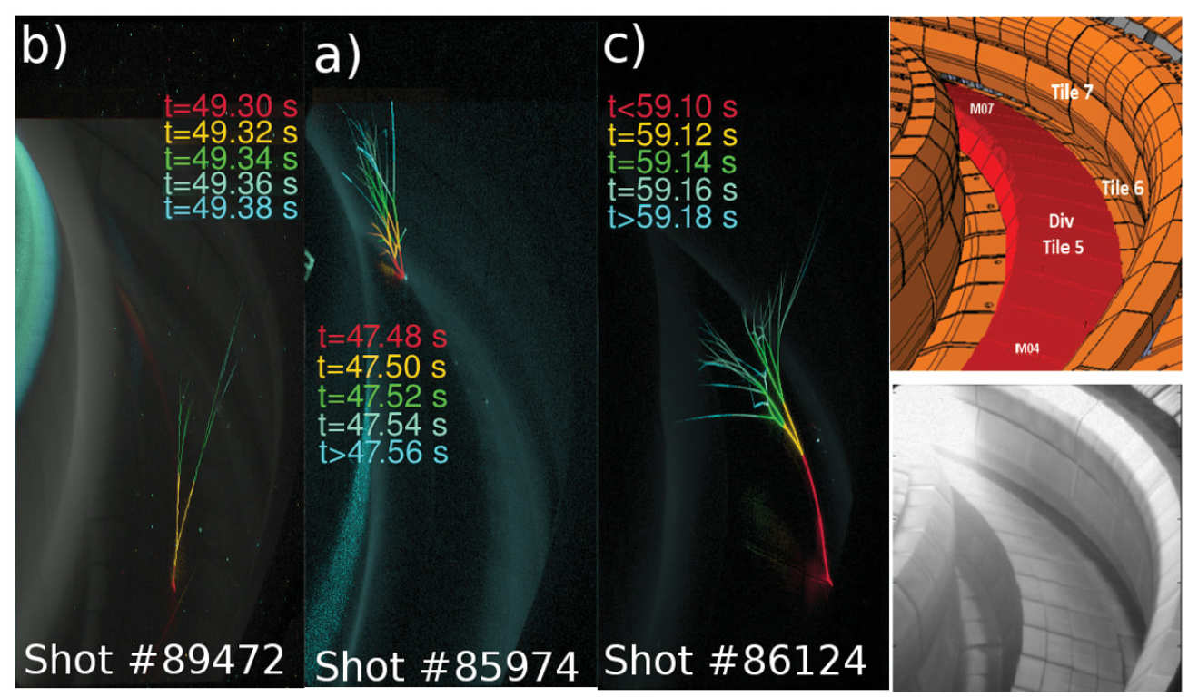
The presence of liquid metal droplets in tokamaks can be inferred from the large quantities of spherical parti- cles, hollow spheres formed from flakes detached from W-coated tiles and resolidified liquid beryllium marks which have been collected from the interiors of the vessels of various machines13–16. Such resolidified metallic spheres are conspicuously absent from the Joint Euro- pean Torus (JET) machine, despite observations of material migration on its visible cameras (see Fig. 1 a-c), which hints at an unexplained mechanism for their destruction or removal exists. Understanding the motion and lifetime of these drops is essential in order to deter- mine the quantity and location of impurities they release in the plasma or redeposit on sensitive surfaces such as diagnostic mirrors17.
H-mode, Pedestal and the L-H Transition
When a magnetically confined plasma is strongly heated and a threshold heating power level is exceeded, it can spontaneously transition from low confinement (or L-mode) to high confinement (or H-mode). In H-mode, the energy confinement time is significantly improved and transport losses from the edge plasma are reduced. The standard operating scenario for the next step tokamak, ITER, is the H-mode. One of the key features of H-mode is an edge plasma pedestal in the temperature, density and pressure radial profiles.
The bifurcation in edge plasma transport is due to the suppression of turbulence in the very thin pedestal region, inside the last Closed Flux Surface (LCFS). There is substantial evidence that the local suppression of plasma turbulence is the consequence of the formation of a layer of sheared flow layer and an associated edge radial electric field. The mechanisms that give rise to sheared plasma flow and trigger the L-H transition is an area of ongoing theoretical and experimental research studies.

H-mode, Pedestal and the L-H Transition
Fig. 2. Formation of the MAST Electron density, temperature and pressure pedestal profiles in the transition from L-mode to H-mode. (Jan-Peter Bahner {MSc.})