Manufacturers of high performance products, such as the aerospace sector, face continuing pressures to improve the performance and reliability of their products and to reduce the development lead times and costs.
Engineering simulation and analysis (FEA, CFD) has become an integral part of the design and development process, while CAD is seen as the backbone for definition and exchange of design information across multiple specialist disciplines.
The research in the Geometric Modelling and Manufacturing Group is addressing the need for seamless integration of methods and tools across a wide range of activities, including:
- engineering design
- simulation
- analysis
- manufacturing process development
- dimensional inspection.
The selected examples presented here show how this is being realised in specific industrial applications.
Case studies and examples
- Design and manufacture of satellite antenna reflectors
- Measurement Based updating of CAD Models
- Robust design
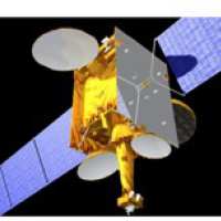 The shape of the satellite antenna reflector is highly complex, dictated by the required geographic coverage of the Radio Frequency (RF) signal. Reflector design employs specialist simulation and optimisation tools. The final shape needs to be represented in CAD compatible format, while ensuring compatibility with the manufacturing process capabilities.
This work with EADS/Astrium has addressed all aspects of the design and manufacturing process and resulted in significantly improved development lead times and quality. This has necessitated the development of a number of new geometric modelling tools.
Original Process:
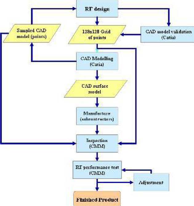
- Point based geometric data exchange
- History, established procedures
- Limitations of legacy tools
Issues:
- Manual shape optimisation for manufacture
- Time consuming RF-CAD iterations involving different departments
- Excessive file sizes
New Process Methodology:
- Surface based (instead of the previous point based methods) leading to improved accuracy and efficiency at al stages of the process
- New computational tools for geometric modelling and shape analysis
- Accurate conversion of surface definition from splines used in RF design to B-splines used in CAD
- Tools for creating CAD model from the RF analysis model
- Tools for RF designers to incorporate manufacturability checks in the RF design iterations
- Seamless interoperability with manufacturers/subcontractors
Measurement data error analysis

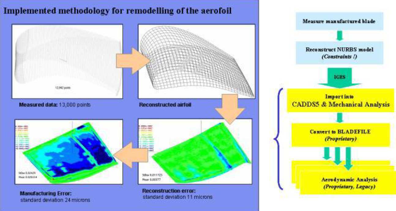
 In the design and development of high-performance products such as turbine blades, it is generally difficult to relate the in-service performance to the specified manufacturing tolerances. For this reason it is highly desirable to perform CAD remodelling of the manufactured part using dimensional measurements, in order to provide an accurate representation of the manufactured geometry. This can then provide input for the engineering analysis tools in order to better evaluate the in-service performance and to correlate the predicted performance with experimental results.
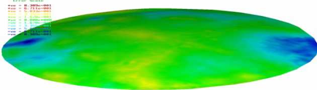
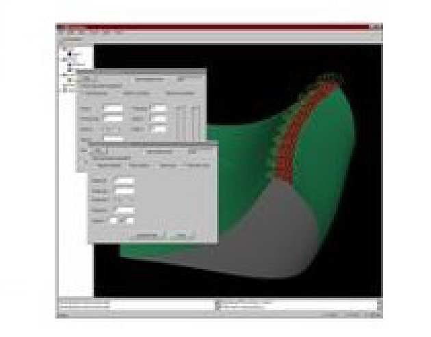
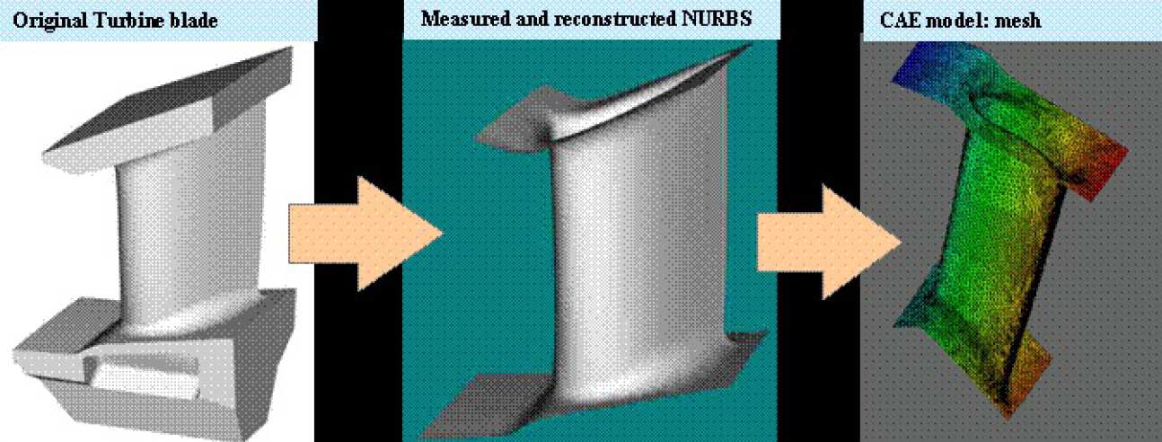
In this application, the CAD model was used to optimise the measurement plan and to program a Coordinate Measuring Machine (CMM) equipped with a touch trigger probe. The measured data was then used to update the CAD model while ensuring that various constraints regarding the shape and the modelling entities were satisfied. The updated CAD model was then used to perform aerodynamic simulation corresponding to the manufactured geometry. The main steps in the process and the results involving the blade aerofoil are presented in the figures below.
In a further step, the above process was repeated, involving all gas washed surfaces of the blade.
Variability in geometry (tolerances), material properties and operating conditions result in the variability of the performance parameters such as the aerodynamic performance of a turbine blade, dynamic performance of the rotor or the life of a component.
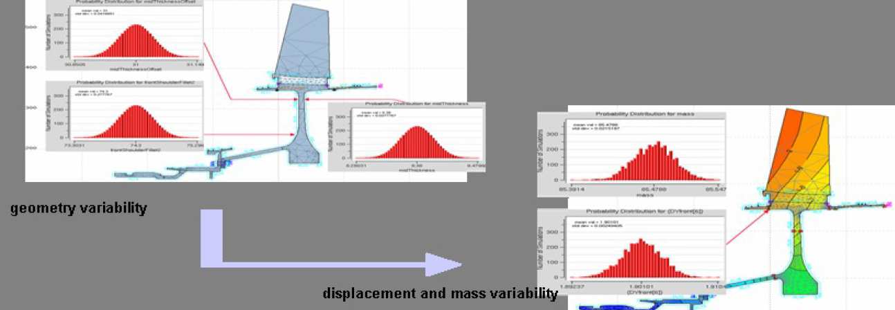
Robust design methodologies extensively employ simulation in order to account for such variability and to:
- Reduce technical risks by modelling complex phenomena's (aero-elasticity, thermal effects, bird strikes, vibrations, etc)
- Reduce testing – avoid additional expense
- Improve efficiency of systems : optimisation of the structures taking into account the engineering criteria (life, mass, vibrations, aerodynamics, etc)
- Analyse potential in-service problems
Methodology
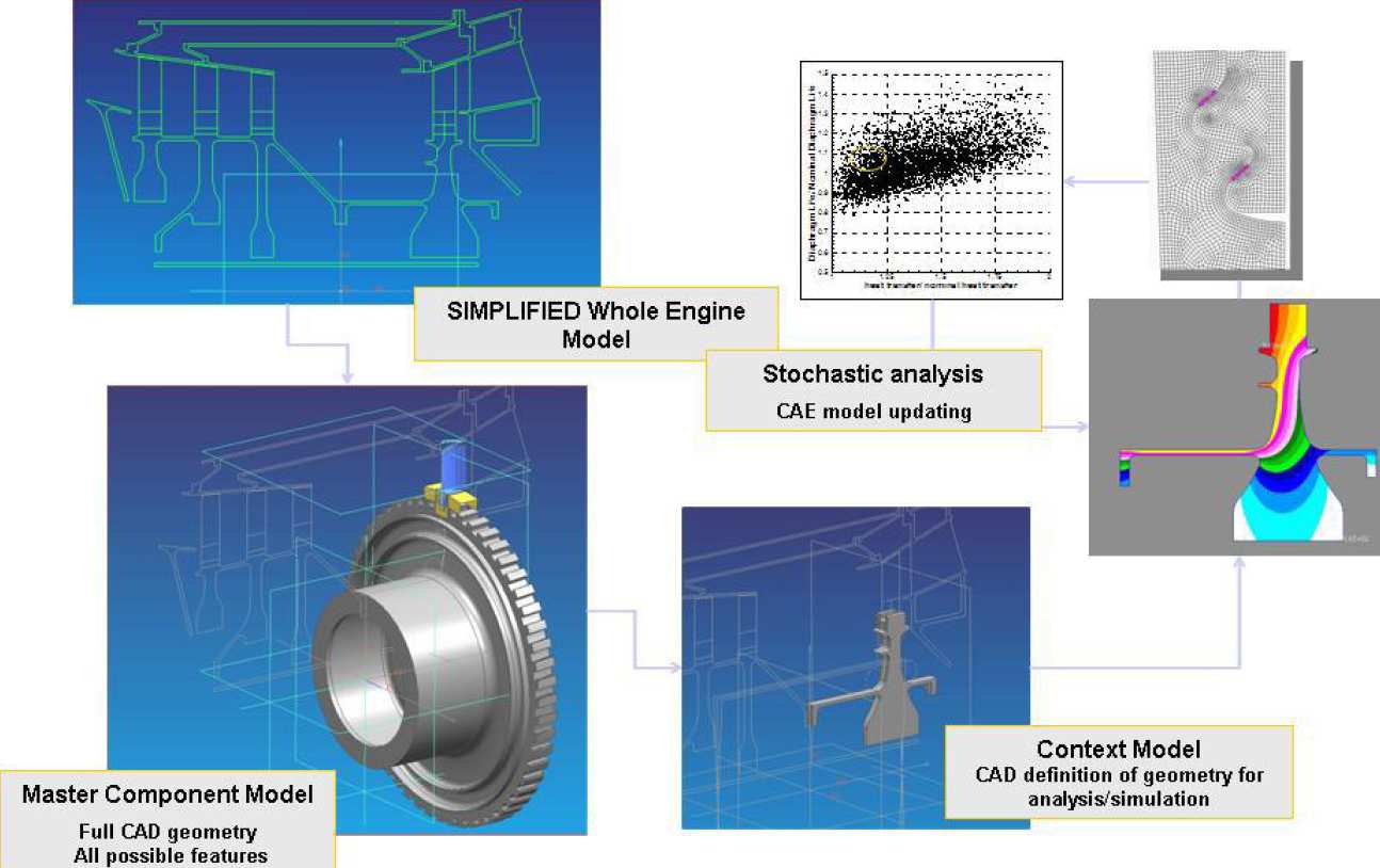
- Optimisation and robust design methodology require the analysis of a great number of different configuration over different parametric Context Models (CM).
- Control Structures represent a flexible an robust tool to build a parametric Master Model (MM) of a component.
- Once the characteristics of the context models are defined, Control Structures can be used to generate and handle both master model and context model.
- Practical implementation of the “links” between MM and CM depends on many factors, for example: the design flow of the component, the tolerances used to build the control structure, etc.
Contact us
Dr. Mihailo Ristic
Senior Lecturer
T: +44 (0)207 594 7048
E: m.ristic@imperial.ac.uk
Dr. Djorje Brujic
Research Fellow
T: +44 (0)207 594 7175
E: d.brujic@imperial.ac.uk