MAGPIE basics
MAGPIE (Mega Ampere Generator for Plasma Implosion Experiments) is a "pulsed power generator", a device which stores up electrical charge in capacitor banks, which can then be rapidly discharged as a very high electrical current in a very short time. MAGPIE consists of four Marx banks (named Groucho, Harpo, Chico and Zeppo) which discharge into four pulse forming lines (PFLs) which then merge into a single vertical transmission line (VTL) which tapers to deliver a 1.4 MA peak current, 250 ns rise time pulse into a vacuum chamber.
The Marx Banks
Marx banks were invented by by Erwin Marx in 1924, and consist of a series of N capacitors which are initially charged in parallel to a given voltage V, and then switched to a series configuration with the output at NxV. Hence, they are an effective method of voltage multiplication. In MAGPIE, our Marx banks consist of 24 capacitors each, six charged to a positive voltage, and six charged negative, the "bipolar Marx" configuration. MAGPIE was originally designed to charge to 100 kV, but this caused significant wear and tear on components, and these days we operate at 65 kV to keep maintainence time to a minimum, resulting in an output voltage of 1.6 MV.
The switches we use to go between the parallel charging configuration, and the series discharging configuration, are gas breakdown switches - two brass electrodes with a brass midplane, separated by perspex cylinders and filled with sulphur hexafluoride, a potent insulator. Each Marx bank is submerged in transformer oil in a metal enclosure around 3 x 4 m and 4 m high.
Pulse Forming Lines
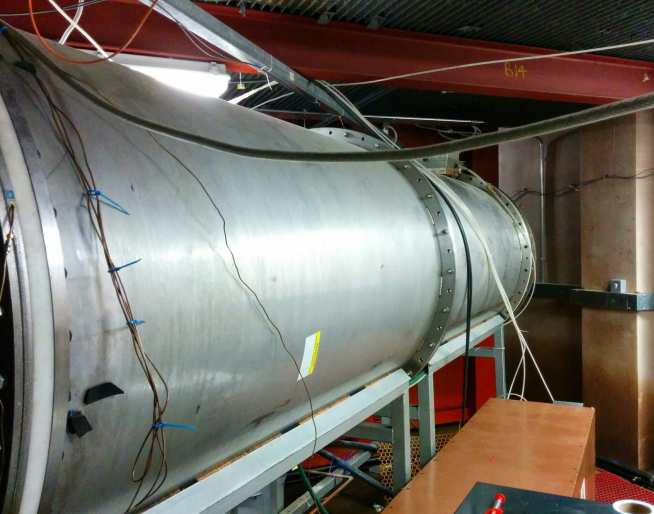
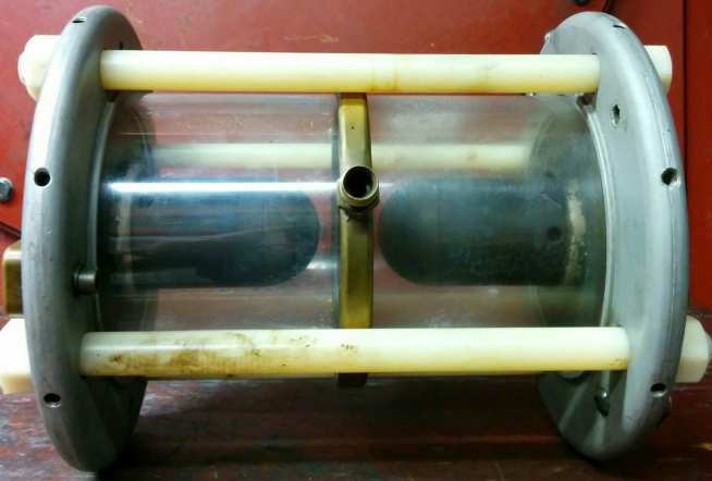
The discharge of a Marx bank is relatively slow, on around a microsecond timescale. In MAGPIE, we want a very fast rising pulse to reach the extreme conditions necessary for x-ray production and laboratory astrophysics. Hence the four Marx banks discharge into four identical pulse forming lines (PFLs), which are coaxial transmission lines 1 m in outer diameter, 3 m long and filled with deionised water. Deionised water is an excellent insulator on short timescales, and easily holds off the 1.6 MV between the inner and outer conductors.
At the far end of each PFL is a large gas (SF6) switch, and the gas switches on each lines are triggered to close simultaneously. One of the electrodes in this switch is hollow, and there is a pin down the axis which sticks out of the end. To trigger the switch, we send a voltage pulse to this pin, which disturbs the local electric fields and causes the switch to break down and close. When this happens, the charge stored in the PFLs flows out as a voltage wave, which discharges each PFL in twice the transit time of the line, around 200 ns.
Vertical Transmission Line
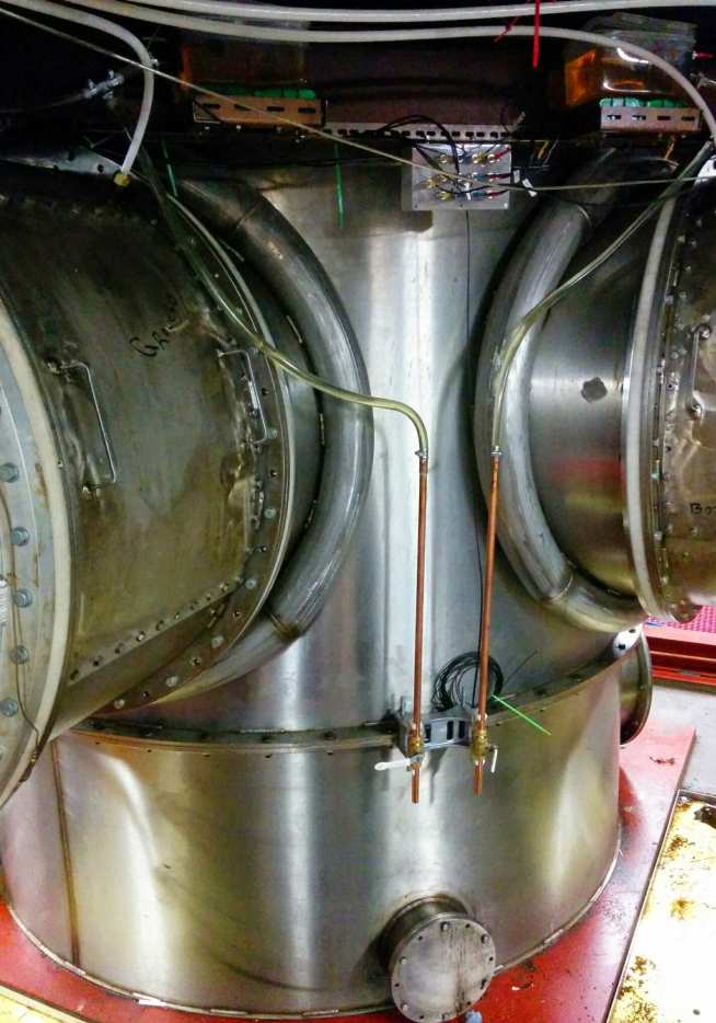
The four PFLs discharge into the Vertical Transmission line, a 2m outer diameter, deionised water filled line around 3 m high. The PFLs have an impedance of 5 Ω, and they charge the 1.25 Ω VTL in parallel, resulting in a peak current of around 1.4 MA. At the top of the VTL, there is a water/vacuum interface in the form of a diode stack, which surpresses breakdown by grading the potential drop using a series of insulator spaced conducting rings.
Inside the vacuum section, the transmission line tapers, and the insulation is magnetic - electrons liberated from the cathode (inner conductor) surface by strong electric fields cannot cross the anode-cathode gap due to the strong magnetic field generated by the mega-ampere currents. The magnetic field returns these electrons to the cathode, and this configuration is known as a Magnetically Insulated Transmission line, or MITL. The top of the MITL appears as a small transmission line, with a 30 mm diameter inner conductor and a 50 mm outer conductor. Here we place the load, surrounded by our plasma diagnostics.
Once the current has passed through the load section, it returns to ground through the outside of the Vertical Transmission Line, and flows back through the PFLs. To protect the capacitors inside the MArx banks from reverse voltages, we have an inline "dump gap", which is an oil insulated closing switch with shaped electrodes, designed to close when the voltage reverses and provide a safe path to ground. When these close there is a spark in the oil, which launches a shock wave which we hear as a loud boom! Therefore, we have a siren to warn the mechanical workshop next door to down tools, and we wear ear protection - it's really loud!
Useful Links