The tokamak is the most successful magnetic confinement configuration for fusion, and many tokamaks exist in laboratories across the globe. At present the largest is the Joint European Torus (JET) located at Culham, but a much larger device, the international next-step fusion tokamak, ITER, is currently under construction in France.
Dust is found routinely in tokamaks, where it forms as a result of plasma-wall interactions, and dust is now recognised as one of the critical issues for ITER. We would like to predict what happens to particles which enter the plasma from surrounding solid surfaces. A particle which enters the plasma from surrounding solid surface and reaches the core plasma will evaporate very rapidly, thus depositing impurities which can compromise the fusion performance. On the other hand, particles which survive long enough to leave the plasma can give rise to serious operational and health and safety problems.
We carry out computational work on tokamak dust transport, using our DTOKS (Dust in TOKamaks) code. This work involves predicting dust trajectories and lifetimes in various tokamaks, including ITER, and comparisons with experiments, and we are constantly improving the physics model which underlies DTOKS.
Tokamak Dust Transport
DTOKS is a dust transport code developed at Imperial College London. It solves the equation of motion of a dust grain in a constant plasma background of the Scrape Off Layer (SOL). The code examines spherical dust grains. The physical model in DTOKS includes three parts: the dust grain charging model, the forces on the dust particle and a heating model including phase changes.
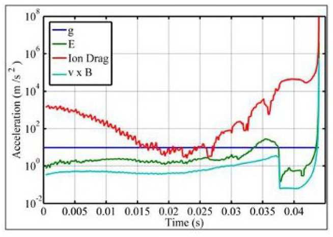
Figure 2: A plot of the forces on a 1 micron Carbon dust particle in MAST, injected from the outer divertor, with an injection velocity of 30ms-1 and for a trajectory where the particle ablates totally within the plasma.
The charging model is based on the OML approach, modified for the case where the dust grain emits electrons. The forces considered include gravity, the Lorentz force and ion drag. The ion drag used in DTOKS is based on the Binary Collision (BC) approach where both the ions scattered in the potential of the grain and the ones collected by the grain are taken into account. The heating model assumes the material properties of the dust grain are the same with the ones of the bulk material, additionally assuming that these remain constant and are not a function of temperature. The kinetic energy flux of the particles hitting the dust grain is then calculated together with the fluxes due to ion backscattering, secondary electron and thermionic emission, neutral recombination and thermal radiation. Based on the calculated energy fluxes the termperature of the dust grain is computed. The model describing phase changes, is based on the temperature of evaporation/sublimation/melting, where the amount of material evaporating/sublimating/melting is calculated by balancing the energy fluxes on the dust grain with the energy needed for a sufficient amount of dust material to change phase.
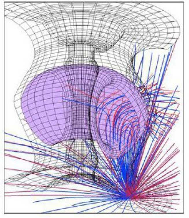
Figure 3: a graphic representation of the trajectories of ions in the potential of the dust grain used for the calculation of the ion drag in the binary collision approach.
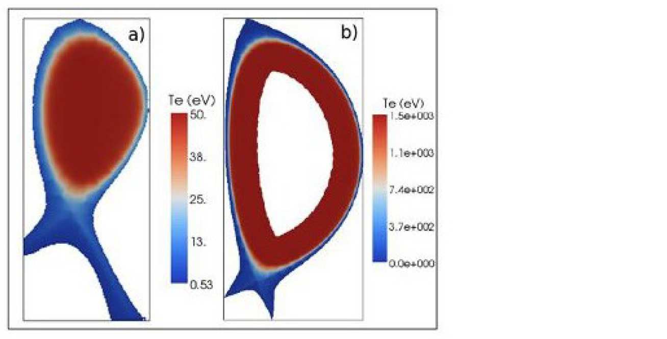
The DTOKS code is currently being updated with new charging models, improved boundary handling and secondary emission as well as time varying plasma backgrounds and edge-events. Some trajectories in the MAST tokamak and ITER divertor are shown.
However, how can uncertainties in the DTOKS physical model or the assumed plasma background affect the accuracy of the DTOKS simulations?
For example the charging model in DTOKS is based on the OML approach. However, there are a few issues raised for the validity of this approach, it was shown though that it is a good approximation for small particles compared with the Debye length. In the case of larger particles a comparison with the more complete Orbital Motion (OM) theory shows differences as high as 50% in the case when the ratio of the ion to electron temperatures is of the order of 1. Furthermore, the situation becomes more complicated in the presence of thermionic and secondary emitted electrons and magnetic fields. Especially in the latter case it has been shown, based on simple considerations, that the presence of a magnetic field can introduce a difference of up to 30% to the OML result for the charge.
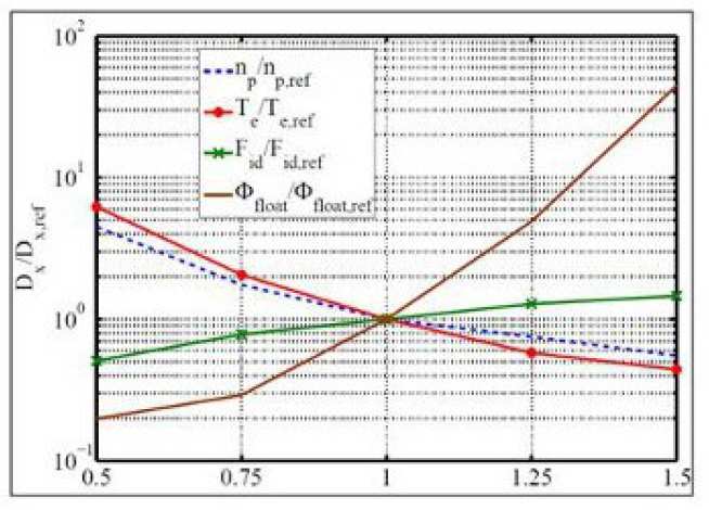
For this reason it is crucial to assess the sensitivity of DTOKS to variations in the plasma background and the underlying physical model, quantifying the impact these parameters have on the predicted particle trajectories. It was found that from the parameters varied, the most important for determining accurately the behaviour of the dust grain within the bounds of the DTOKS model was; (1) the floating potential, (2) the electron temperature, (3) the plasma number density and (4) the ion drag.
Figure 4: Plot of the normalised distance, D, travelled by the dust grain in the x direction as function of the ratio of the corresponding plasma parameter to its reference value. The parameters investigated are the plasma number density, the electron temperature, the ion drag and the floating potential of the dust grain.
An important aspect of our ongoing study of the dynamical behaviour of dust particles in a tokamak environment is the benchmarking of DTOKS against experimental data. Despite the challenging nature of these experiments the use of twin camera systems makes possible 3D reconstruction of dust trajectories observed in a tokamak during operation. The Mega-Amp Spherical Tokamak (MAST), based in the Culham Science Centre in Oxfordshire is ideal for such experiments because of the excellent diagnostic access it provides.
As part of the dust related program in MAST, dust injection experiments have been carried out. These experiments included the introduction of distributions of Carbon and Tungsten dust particles using the Divertor Science Facility (DSF). In each experiment the dust particles were loaded on the DSF head and were raised inside the MAST vacuum vessel, where they were mobilised by the plasma and their trajectories were observed using stereoscopic imaging. The experiment provided an array of observed dust trajectories of Carbon and Tungsten particles that can be compared with the ones calculated by DTOKS tha t allow the benchm arking of the code. The first results of this comparison showed that there is good qualitative agreement between theory and experiment. A more detailed comparison is currently underway.
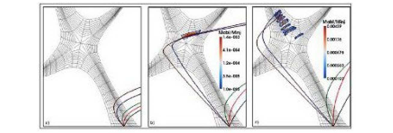
Figure 5: Trajectories of Carbon dust particles injected from t he strike point of the outer divertor in a MAST plasma background with a radius rd = 1μm with initial injection velocity of: (a) vinit = 10ms-1(b) vinit = 25ms-1 (c) vinit = 40ms -1
An important aspect of the study of dust transport in tokamaks is the dependence of their dynamical behaviour on the material properties of the solid particles. In ITER various scenarios have been considered for the construction of the divertor and first wall. All these scenarios are planned to be adopted in various stages of the project's development. These options in chronological order are the following. First, a combination of CFC, W and Be for the divertor and the first wall. Second, a W divertor with Be first wall and third an all W vessel. Because of the limited operational experience with W and Be extensive modelling of their behaviour is of great importance. An aspect of this effort is the modelling of the behaviour of W and Be dust particles. A question of paricular importance because unlike Carbon (C) both W and Be have a liquid phase and Be is especially sensitive to heat loads.
Motivated by these considerations, we used DTOKS to investigate the behaviour of Tungsten (W) and Beryllium (Be) dust particles in ITER. With the main focus being the study of the impurity deposition profiles for Tungsten and Beryllium particles in the ITER plasma as a function of the dust material, initial size and injection velocity. Furthermore, under which conditions it is possible for dust particles to reach within the separatrix was investigated. It was found that smaller particles with lower injection velocities deposit most of their initial mass within the plasma. Second, larger particles, with high injection velocities have a higher probability of reaching the Last Closed Magnetic Surface (LCMS) and the core.
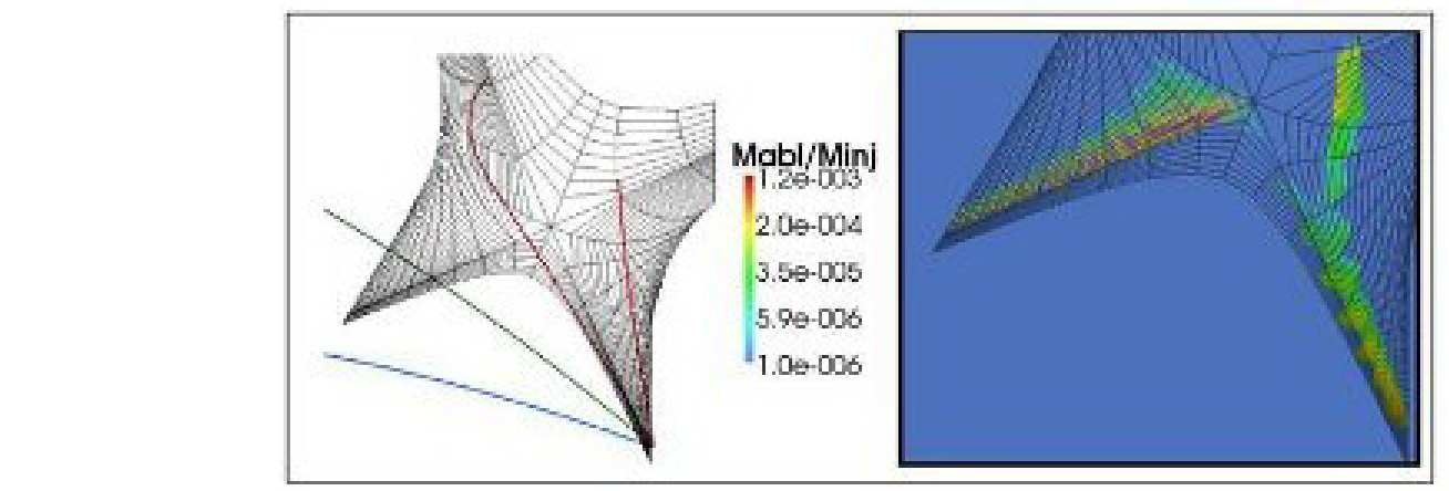
Figure 6 (left): Representative dust trajectories (right) and a plot of the mass of dust ablated in the plasma (Mabl) as a fraction of the total injection mass (Minj) by a cosine distribution of Tungsten particles with a radius of 100μm injected from the outer divertor (left).
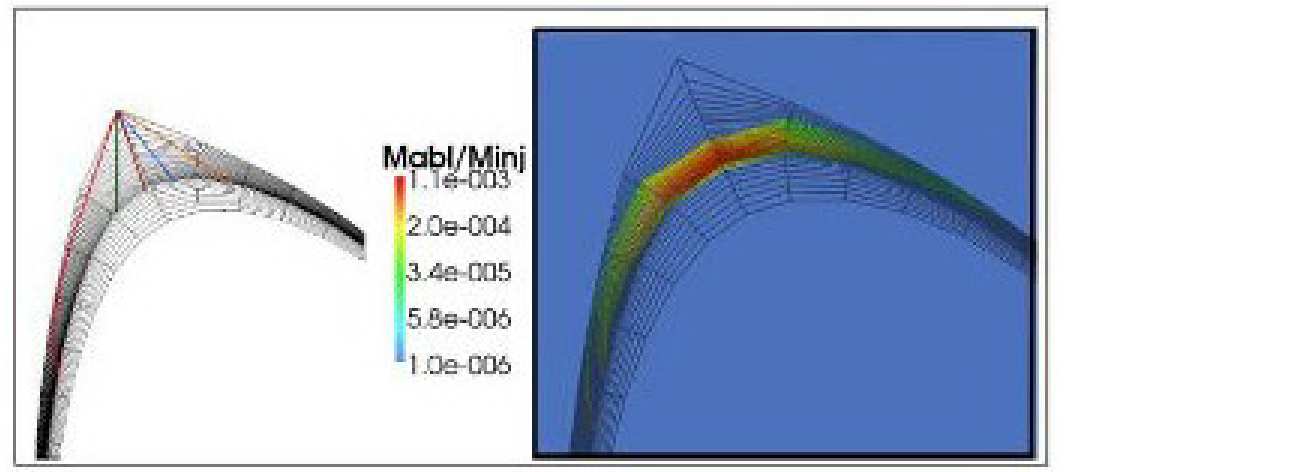
Figure 7 (right): Representative trajectories (right) and a plot of the mass of dust ablated in the plasma (Mabl) as a fraction of the total injected mass (Minj) by a cosine distribution of Beryllium particles with a radius of 100μm injected from the top of the vessel (left).