Kinematic Models

In the following modeling description, it is assumed that trajectories are defined in a plane and that the probe, which is aligned with the plane during an initial setup, is composed of two identical segments. Webster, III, et al. showed that the kinematic model of a bevel tip needle could be considered to be similar to that of a bicycle model with a fixed steering angle [1]. In the case of our probe, the steering direction can also be altered using the offset between the two segments, and the kinematic model can, thus, be considered to be similar to that of a bicycle able to steer.
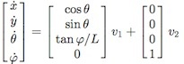 In the model, x, y, θ, and φ indicate the x-axis coordinate, y-axis coordinate, the approach angle, and the steering angle of the bicycle model, respectively, and v1 , v2 , and L indicate the forward velocity of a bicycle’s body, the rate of change of the steering angle, and the distance between front and rear wheels, respectively.
In the above model, the relationship between the forward velocity v1 and the rotational velocity θ ̇ determines the instantaneous curvature ρ of a real trajectory, and it is a function of the steering angle φ, i.e., ρ = tan(φ)/L [2]. Contrary to the bicycle model, however, in our probe, the instant curvature is assumed to be a function of the steering offset δt at the tip of the probe, as follows:
ρ = f(δt) ≡ κδt
Where f(δt) is empirically assumed to be a monotonically increasing function of the steering offset.
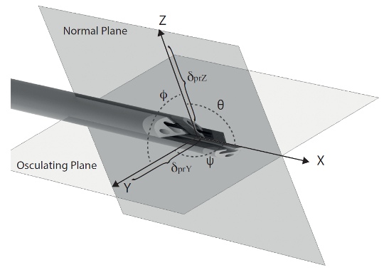
In the 3D kinematic model, a similar assumption as in the 2D Model, has been made for both the osculating and normal planes (see Figure), with the assumption that the ”effective steering offset” in 3D, which is a definition we use to describe how the different relative offsets between segments work together to produce a single overall tip orientation, is a function of all 4 parts of the needle.
As in the 2D model, the curvature in the osculating plane as well the torsion in the normal plane have been defined as proportional function to the virtual offset projection in the corresponding planes.
The full kinematic model is reported as follow:

with v1 the cruising speed and v2 and v3 the relative speed of the segments in order to change the projections at the tip of the probe.
K1 and K2 are linear coefficients obtained by experimental calibration [1/mm]
Offset-Curvature Relationship
We have shown, previously [3], the concept of the ‘Programmable bevel’ where the steering angle of the needle, related to the curvature of the path taken, is a function of the offset between segments in 2D (Offset-Curvature relationship). We showed that this relationship is approximately linear between a bounded set of offsets. In the kinematic models above this is represented by setting κ to a constant.
Recently we have shown that relationship extends to 3D with a single segment protruding [4]. We also compared the results of a single segment with that of two protruding segments (the 2D case). The graph below shows these results, showing that there is a difference between the two Offset-Curvature relationships.

[1] Webster, Robert J. and Kim, Jin Seob and Cowan, Noah J. and Chirikjian, Gregory S. and Okamura, Allison M.. Nonholonomic Modeling of Needle Steering. . p. 509-525 2006
[2] Kallem, V.; Cowan, N.J., "Image Guidance of Flexible Tip-Steerable Needles," Robotics, IEEE Transactions on , vol.25,
no.1, pp.191,196, Feb. 2009
[3] Seong Young Ko; Frasson, Luca; Rodriguez y Baena, F., "Closed-Loop Planar Motion Control of a Steerable Probe With a “Programmable Bevel” Inspired by Nature," Robotics, IEEE Transactions on , vol.27, no.5,pp.970,983, Oct. 2011
[4] C. Burrows, R.Secoli, F. Rodriguez y Baena, "Experimental Characterisation of a Biologically Inspired 3D Steering Needle," Control, Automation and Systems (ICCAS), 2013 13th International Conference on, 20-23 Oct. 2013
Contact details
Prof. Ferdinando Rodriguez y Baena
Co-Director Hamlyn Centre, Professor in Medical Robotics
Prof. Brian Davies
Senior Research Investigator