The Department of Aeronautics came into being in the autumn of 1919 when Sir Richard Glazebrook FRS accepted the invitation to become its Head. During the 100 years since its establishment, the Department has been engaged in experimental work related to various aspects of aeronautics. One such area is low speed aerodynamics, made possible by having access to a wide range of wind tunnel facilities.
The wind tunnels that were in use after the 1950s are relatively well documented, far less is known about the facilities available during the Department’s first 40 years. Sir Richard Glazebrook was superseded in 1923 by Sir Leonard Bairstow FRS, renowned for his research in low speed aerodynamics. He had close connections with the National Physical Laboratory at Teddington and publications indicate that wind tunnels at the NPL, which could be reached relatively easily from Imperial College, were used from time to time for research by Imperial staff. Sir Leonard Bairstow was followed as Head of Department in 1943 by Sir Arnold Hall FRS and during his headship he secured funding for a new aerodynamics laboratory.
This laboratory, which opened in 1951, included new wind tunnel facilities which served the Department well for sixty years. A further significant development occurred in 2017 when the Department moved from the Roderic Hill Building and the ACE extension to the refurbished City and Guilds Building. Funding was provided by the College to replace two of its existing low speed tunnels.
1925 - The first wind tunnel in the Department of Aeronautics
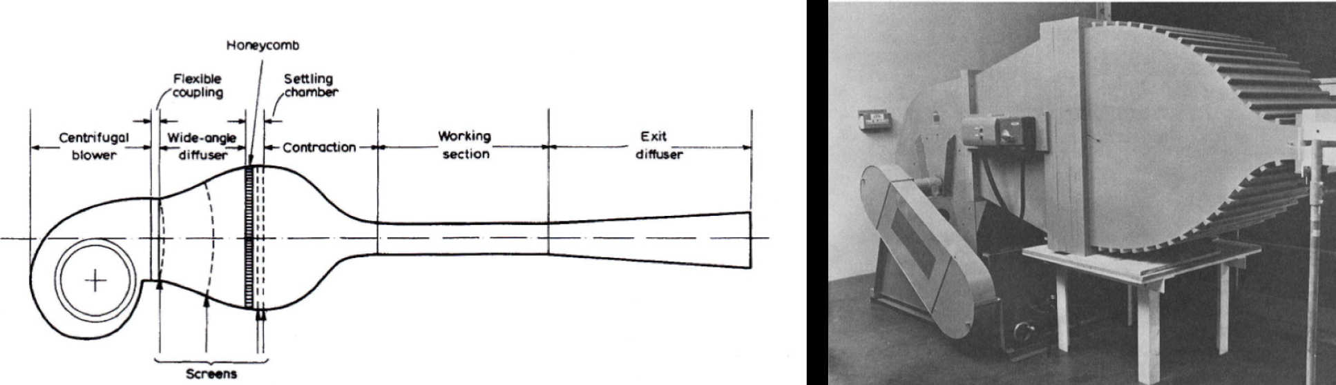
The first wind tunnel in the Department is reported as having become operational in 1925. It is known that the tunnel was relatively large with a working section 5’ x 4’ (1.52 m x 1.22 m) and that it had an open-return circuit, a design known as the NPL type.
The diagram shows the layout of a typical NPL type open-circuit wind tunnel. Unfortunately no photographs or drawings could be found of the Imperial College wind tunnel. It is known that one of the reasons for building the tunnel was to test models of airships, considered at the time to be important for the future of air transport.
1931 - The 2' open jet tunnel
In 1931, a second low speed wind tunnel was built, known as the 2 ft (0.61 m x 0.61 m) open jet tunnel. This had an open test section but it has not been possible to confirm if it was of the open or closed return circuit type.
As with the 5 x 4 tunnel, no detailed information on the tunnel’s performance appears to remain. A paper by G.J. Richards published in 1934 in Philosophical Transactions of the Royal Society shows that, in addition to wind tunnels, low speed experiments were being carried out in a water facility using an early form of particle image velocimetry. The drawing shows the ‘Imperial College Fluid Motion Apparatus’, as it was called. The water tank was 3.66 m long, 0.46 m high and 0.3 m wide.
It was used primarily to compare measurements of flow fields around bodies at low Reynolds numbers with predictions from solutions of the equations of motion. Bodies were drawn along the tank at constant speed and flow velocities found by seeding the water with particles and recording their paths on a photographic plate exposed for a suitably short duration. Before returning to the subject of low speed wind tunnels it should be noted that the Department has used water facilities for fluid mechanics’ research up to the present day.
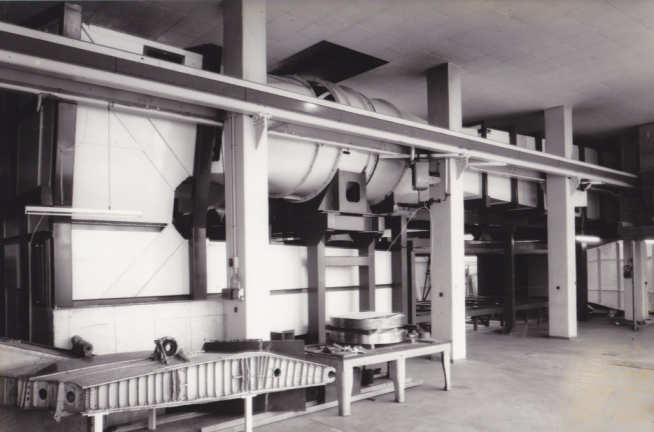
1951 - The new 5' x 4' Donald Campbell Wind Tunnel
One of the outcomes of the additional funding for laboratories obtained by Sir Arnold Hall was the acquisition of a replacement 5 x 4 wind tunnel in 1951.
The new closed return tunnel was equipped with an overhead, three component balance and had a top speed of 50 m/s.
From around 1960, an important feature of this tunnel became its rolling road. The apparatus was obtained from RAE Farnborough by Professor John Stollery for testing related to the land and water world record attempts by Donald Campbell. It was also used for the design of the Intercity 125 train and for improving the aerodynamic performance of Formula One racing cars.
Following Campbell’s fatal accident on Coniston Water the tunnel was renamed the Donald Campbell Wind Tunnel in his memory. In 1964, P. Bradshaw and R.C. Pankhurst of the NPL published a comprehensive paper on low speed wind tunnel design and the airline diagram of the 5 x 4 tunnel is from their paper. With the move of the Department of Aeronautics to the City & Guilds Building in 2017 the Donald Campbell Wind Tunnel was offered to the University of Nottingham.
The 3' x 2' and the 20" closed return tunnel
A paper by Dr Alan Taylor-Russell, published in Aircraft Engineering, provides valuable information on experimental facilities in the Department up to 1963. In addition to the 5 x 4 wind tunnel he briefly describes two other low speed, closed return tunnels that were used for teaching and research.
One was known as the 3 x 2 and had a working section 1 m high by 0.58 m wide and a top speed of 40 m/s. Due to restricted space this tunnel had an unusual arrangement for the fan-drive system with the motor outside the tunnel, the fan shaft entering at right angles to the flow and gearbox to transmit the drive to the fan. In 2009 this tunnel was deemed to be no longer required and was scrapped.
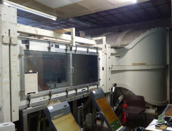
The other closed return tunnel, the 20 inch, originally had a 0.51 m wide, regular octagonal test section and a top speed of around 60 m/s. It is thought that the tunnel was built as a model for the 5 x 4 Donald Campbell tunnel. The 20 inch tunnel was later modified to have a rectangular test section, as shown in the photograph, and is still in use.
1965 - The 3' x 3' Wind Tunnel
During the 1960s, it was decided the Department needed an additional low speed wind tunnel with good flow uniformity and a low free stream turbulence level. Dr Les Bradbury, 1965 – 1970, was responsible for the design and supervised much of the construction of a 3’ x 3’ (0.91 m x 0.91 m) wind tunnel but moved to the University of Surrey before it was completed.
Apart from the fan which was made at RAE Farnborough, the tunnel was constructed in house by the Department’s carpenter, Jack Beasley. It became operational in 1971 and was much sought after for research student projects.
The top speed was 45 m/s and the turbulence level was only 0.05%. The test section was 5.5 m long and this made it attractive for wake studies. At the time of writing, the tunnel is still operational but with the Department’s move to the City & Guilds Building it is not considered practical to relocate it and it is planned to be scrapped.
1969 - The development of the "Bradshaw" blower
In 1969 Professor Peter Bradshaw FRS moved from the National Physical Laboratory to join the Department of Aeronautics where he designed and built a number of compact blower tunnels ideally suited to advancing understanding of turbulent boundary layers.
1985 - The 10 x 5 Honda tunnel
In the latter half of the 1970’s, a time of increasing oil prices, road vehicle manufacturers became acutely aware of the need to improve aerodynamic performance in order to reduce fuel consumption.
It was around this time that the Department entered into a research contract with the Honda R & D Company to improve knowledge of passenger car aerodynamics, including the effects of the natural wind on the forces and moments experienced by a car.
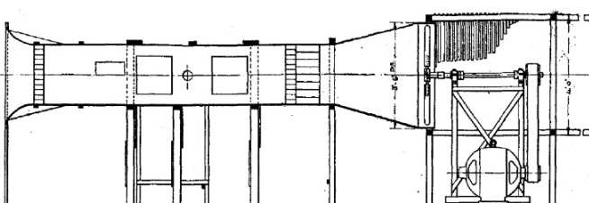
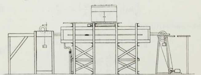
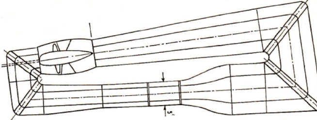
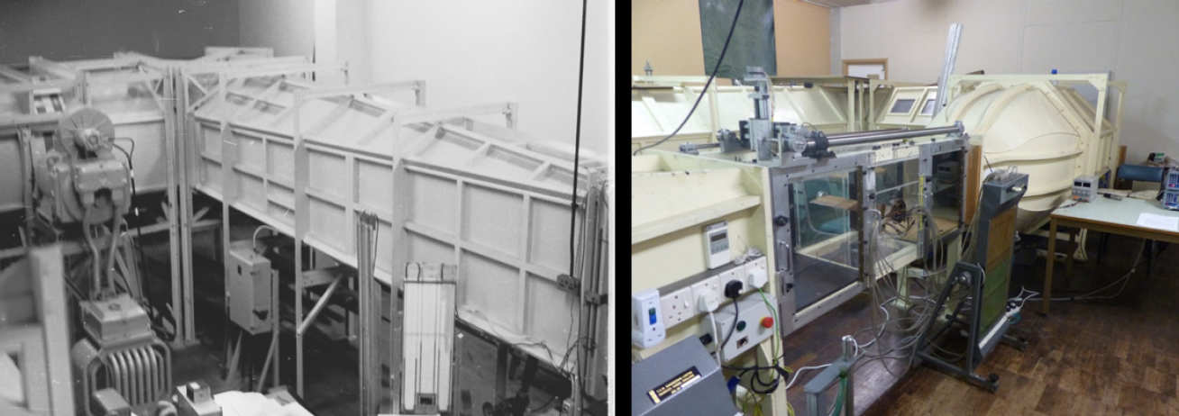
The contract included the building of a large low speed wind tunnel with a rolling road suitable for testing 1/3 scale models of passenger cars. This tunnel, known for many years as the Honda Tunnel, had a test section 10’ wide, 5’ high and 29’ long (3 m x 1.5 m x 9 m).
In order to minimise the lab floor area required, it was designed with the return circuit containing two fans situated directly above the test section. Initially the maximum speed was 35 m/s and some 20 years later the motors were upgraded to increase the top speed to 45 m/s.
Professors Peter Bearman and John Harvey were responsible for the airline design and supervised the building of the tunnel. During construction the founder of the Honda Motor Company, Mr Soichiro Honda, visited twice.
The tunnel was officially opened in July 1985 by the Managing Director of the Honda Motor Company, Mr Fujio Ishikawa. When the research programme sponsored by Honda was completed the company passed full ownership of the tunnel to the College.
Officially the tunnel now became the 10 x 5 but is still frequently referred to as the Honda tunnel.
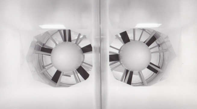
2017 to present - The move of the Department of Aeronautics to the City and Guilds Building
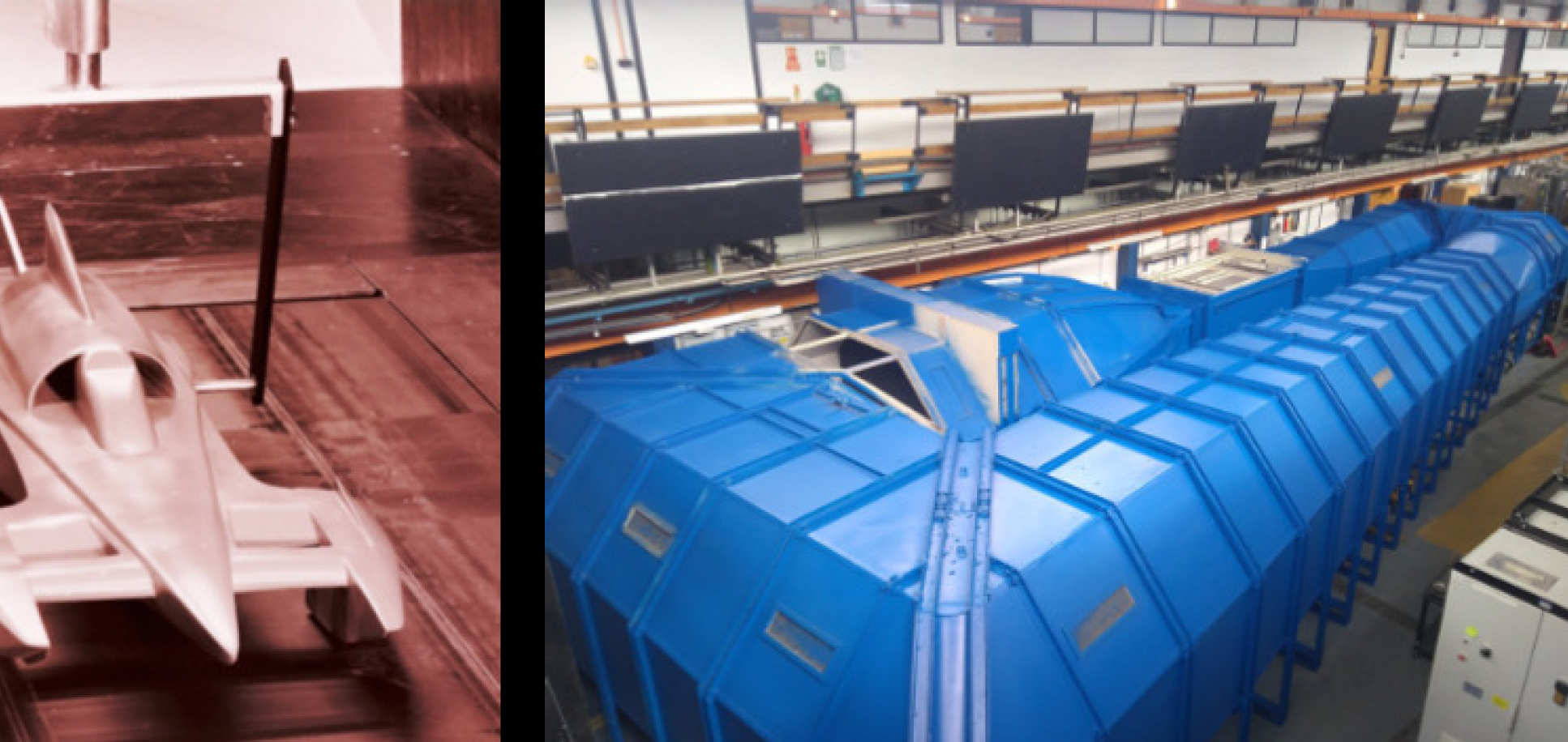
In 2006, the College made the decision to relocate the Department of Aeronautics in the City & Guilds Building. The building, previously known as the Mechanical Engineering Building, underwent a complete refurbishment and the Department did not complete its move until 2017. This development brought into question the future of the aging Donald Campbell wind tunnel, the 3 x 3 and the 10 x 5 tunnels. The College came to the rescue by providing funding for a replacement 3 x 3 tunnel and a new general purpose low speed tunnel to replace the Donald Campbell tunnel, known at the time of writing as T1 and T2 respectively. In order to fit the two tunnels into the lab allocated in the City & Guilds Building it was necessary to construct T1 and T2 as ‘up and over’ tunnels and to mount them side by side with a common control room.


