Micro mechanical devices
- Silicon Electrostatic Microactuators
- Bulk-micromachined Thermo-hydraulic Microactuator
- Micro Dynamics
- Passive Frequency Tuning of Microresonators
- Active Frequency Tuning of Microresonators
- Electrostatic and Mechanical Modelling of Electroformed Structures
- Improved Design of Micromachined Lateral Suspensions using Intermediate Frames
- Differentially Cooled Electrothermal Micro-actuators
- MEMS Vernier Latch Mechanisms
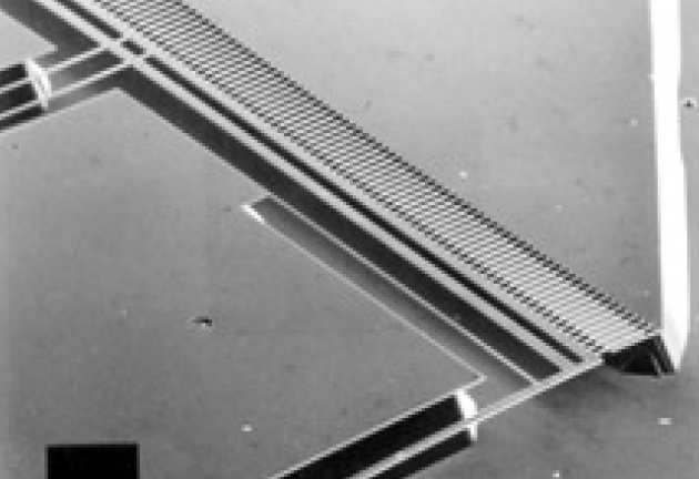
Because electrostatic forces scale relatively advantageously with reducing size, electrostatic actuators are promising alternatives to electromagnetic devices in the microstructure size domain. Silicon-based surface micromachined actuators have already been demonstrated, using polysilicon mechanical parts on a silica sacrificial layer. We have developed an alternative fabrication process, based on bulk micromachining of silicon. A 7 microns deep p+ etch stop layer is first formed by boron ion implantation and diffusion into an n-type wafer. This layer is then patterned with a Cr metal mask, and reactive ion etching is used to transfer the pattern through the etch stop layer. A wet chemical etch (EDP) is then used to remove bulk silicon to a considerable depth (100 microns) beneath the mechanical parts, to create an undercut structure that is free to move on a flexure suspension system. Mechanical motion is obtained by applying electrostatic forces through pairs of comb-drive electrodes, using electrode isolation provided by inbuilt p-n junction diode structures. Single-axis devices have been constructed which have displacements as large as 20 microns at resonance, using drive voltages of ~15 V.
 |
|---|
| Bulk micromachined electrostatic microactuator. |
 | ||
|---|---|---|
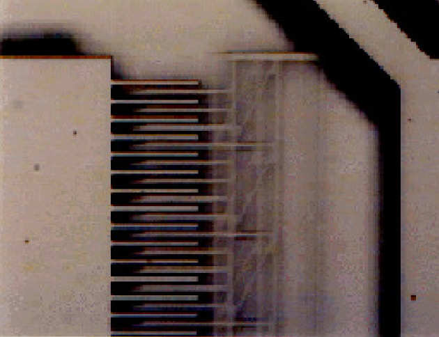
| View of comb electrodes in motion. |
Jun Su Lee and Stepan Lucyszyn
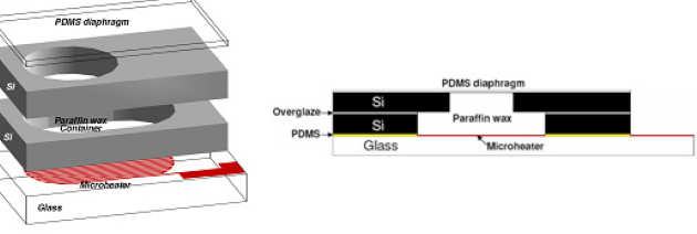
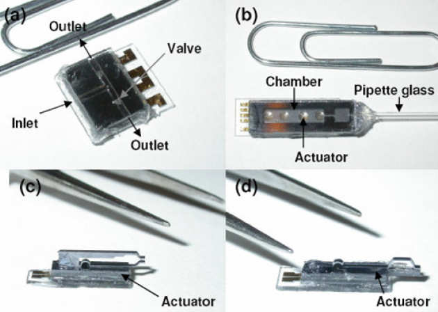
Paraffin wax exhibits a volumetric expansion of ~15%, at around its melting point. A high performance bulk-machined hydraulic electrothermal microactuator activated using paraffin wax has been fabricated. As applications, the actuators have been applied to Braille cells, microfluidic valves, microgripper and micropipette. The paraffin wax is contained within a bulk micromachined silicon container. The container is sealed using an elastic diaphragm of PDMS. The container is heated using gold microheaters located on an underlying glass substrate. All the layers used to make up the containers are bonded together using an overglaze paste and PDMS. The all application devices were successfully operated at around 10 or 15 V.
 |
|---|
| Expanded structure of the basic bulkmicromachined actuator, and cross section of the actuator. |
 |
|---|
| Assembled devices: (a) microvalve, (b) micropipette, (c) microgripper of type A and (d) type B. |
Richard Syms, Ty Harness
 |
|---|
| Bulk micromachined x-y stage. |
 |
|---|
| CAD layout of 2-axis comb-drive electrostatic microactuator. |
 |
|---|
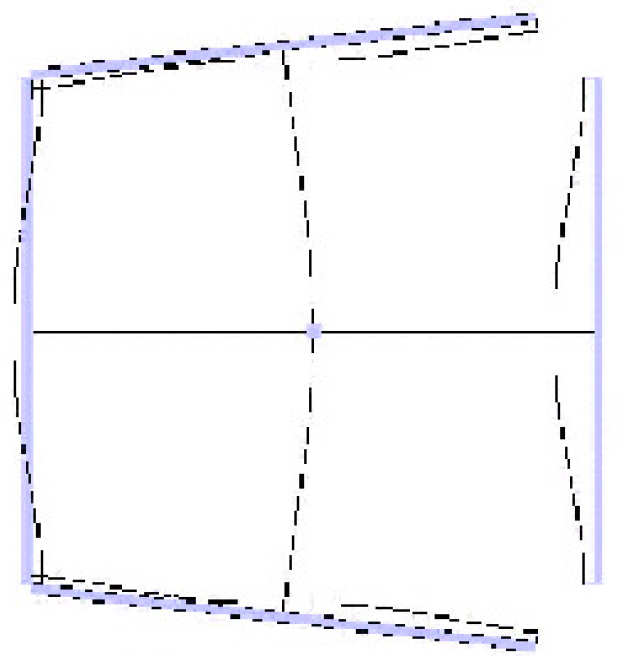
| ANSYS plot of lowest order hybrid resonant mode of 2-axis microresonator. |
Richard Syms, David Moore (Cambridge University)
Vibrating resonators are important components of micromechanical systems, with applications in sensors and actuators. However, defects and stresses can cause resonance shifts, and it is important to develop methods of tuning. Active tuning is based on electrically-induced stress. We have developed simple electrothermal tuning methods, and have used them to demonstrate wide-range, reversible tuning of single resonators (up to 50% change in resonant frequency), and also independent frequency tuning and matching of coupled resonators.
 |
|---|
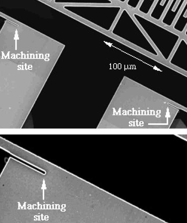
| In-plane microresonator, after FIB tuning. |
Passive methods are based on dimensional trimming, and are potentially more economic, since they avoid the need for control circuitry. However, care is needed to optimise the tuning process. We have demonstrated precise tuning of in-plane microresonators by using focused ion beam (FIB) micromachining to remove material at the roots of flexure suspensions, and hence effectively lengthen the flexures.
 |
|---|
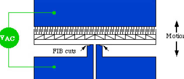
| Layout of in-plane microresonator. |
 |
|---|
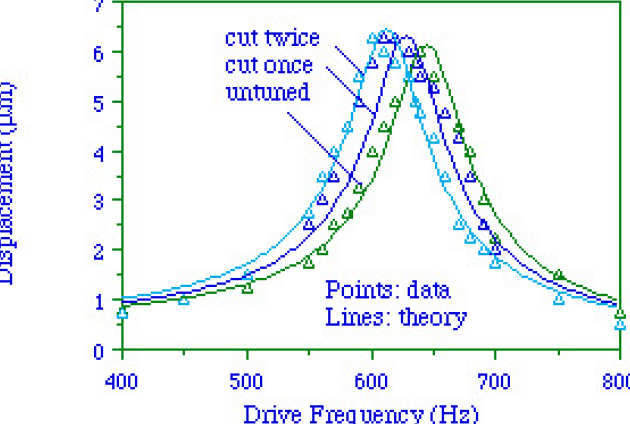
| Frequency response, before and after FIB micromachining. |
 |
|---|
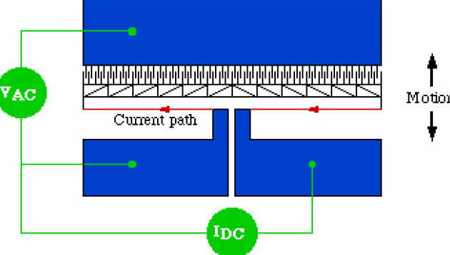
| Arrangement for electrothermal tuning of single-axis resonator. |
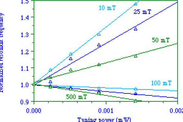 |
|---|
| Variation of resonant frequency with tuning power, at different external gas pressures. |
Resist moulds formed by UV lithography generally have sloping sidewalls, which are transferred to electroplated structures. As a result key elements in resonant electrostatic devices, such as support beams and comb-drive electrodes, are trapezoidal rather than rectangular in cross-section. We have investigated the effects of non-vertical sidewalls on the mechanical constants of nickel beams, and on the performance of electrostatic comb-drives. In the former case, the effect is to reduce the torsional stiffness of the beam. In the latter, asymmetry of the fringing fields above and below the electrodes, and in the field in the gap, causes out-of-plane actuation forces to arise. These may be used to excite torsional motion in suspensions normally driven in-plane. The figures below show the variation of the normalised torsional stiffness, and the vertical force, with wall angle in trapezoidal cross-sections.
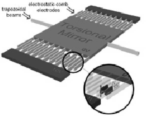 |
|---|
| Trapezoidal features in a typical torsional mirror microstructure. |
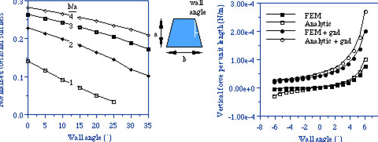 |
|---|
| Variation with wall angle of a) the normalised torsional stiffness kt x L/a3bG (where L = beam length, and G = shear modulus), and b) out-of-plane electrostatic force (with a = 15 microns, b = 4 microns, and minimum gap = 4 microns). |
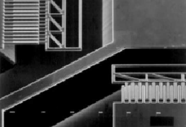
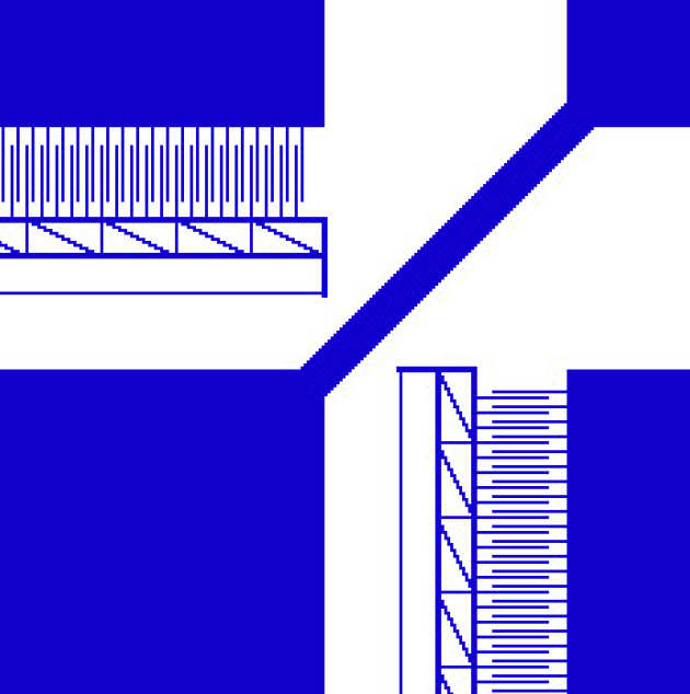
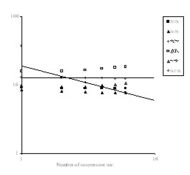
Lateral suspensions are one of the most common types of structures used in MEMS devices. We have performed the first complete analysis of the translational and rotational modes of a model lateral suspension. The derived formulas quantify spurious-mode resonant frequencies for cross-axis translation and rotation, and on-axis translation, and can provide very simple expressions for the rejection ratios in terms of the geometry of the suspensions. It is shown that the introduction of intermediate frames, coupling equivalent points of the lateral suspension either side of the suspended mass, can provide much improved dynamics.
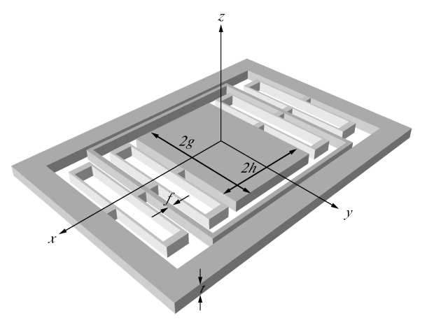 |
|---|
| A lateral suspension incorporating an intermediate frame |
Below are shown how the rejection ratio falls off rapidly for all the off-axis modes as more folded cantilevers are added to the suspension without frames, while with frames the rejection ratio is maintained.
 |
|---|
 |
|---|
To investigate the derived relationships suspensions have been fabricated using through-wafer deep reactive-ion etching (DRIE). Using analysis of the suspension dynamics under the rastered beam of a scanning electron microscope, the various modes of the suspension have been visualized and quantified. These observations are in good agreement with the derived formulas, taking into account the actual profile of the beams fabricated in DRIE. Further finite element analysis across a broad range of suspensions is consistent with the derived formulas. A design heuristic is provided for rapidly optimizing micromachined lateral suspensions by incorporating intermediate frames.
Hadi Veladi, Richard Syms and Helin Zou
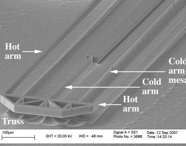
We have developed a simple method for increasing the thermal efficiency of shape bimorph electrothermal micro-actuators, based on a reduction of gas conduction cooling beneath the hot arms by a deep, localized undercut. We have demonstrated a single-sided, single-mask SCREAM-type process for fabricating differentially cooled actuators in bonded silicon-on-insulator material. The process uses deep reactive ion etching and undercut to form suspended parts and isotropic reactive ion etching and lift-off of sacrificial shields to form localized mesas. The advantage of the method has been confirmed using folded electrothermal actuators, and an approximate halving of the drive power has been demonstrated by variations of the substrate profile.
 |
|---|
| Process for forming shape bimorph electrothermal actuators with local cooling mesas. |
 |
|---|
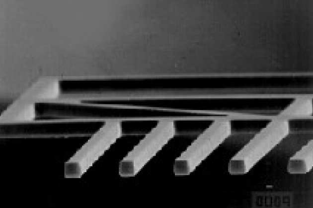
| SEM view of free end of device. |
Richard Syms, Helin Zou and John Stagg
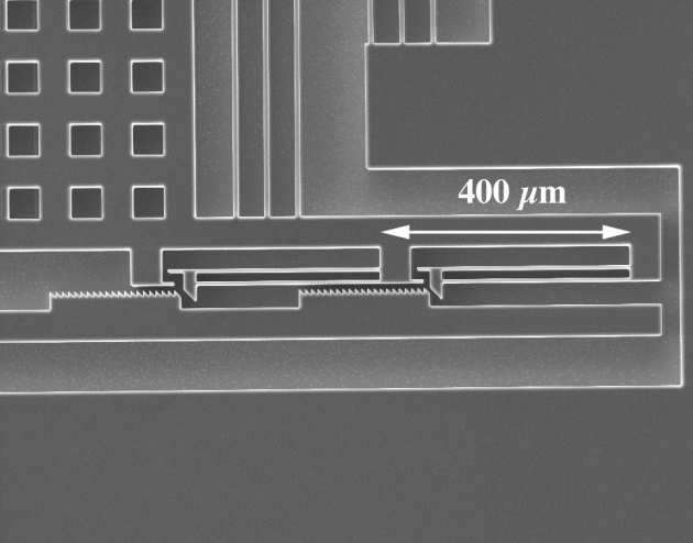
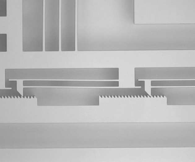
We have constructed latching MEMS alignment stages by deep reactive ion etching of bonded silicon-on-insulator material, with linear, rotary and tilt mechanisms. Linear stages are driven using buckling electrothermal actuators, and latching is performed by a rack and tooth mechanism driven by shape bimorph actuators. In-plane rotation has been obtained by using a linear actuator to drive a passive rotary table, and tilt motion using an inserted mirror. A rack period of 10 µm has been achieved with a structural depth of 85 um. A Vernier mechanism based on multiple latches has been used to increase precision beyond the value set by pattern transfer.
 |
|---|
| SEM photograph of two-section Vernier latch. |
 |
|---|
| Optical photograph of two-section Vernier latch in operation. |