Micro electrical devices
- 3-D Self Assembly of Microwave Inductors
- Energy Scavenging from Rotating Motion
- Evaluating Surface Impedance for Terahertz Frequencies at Room Temperature
- MEMS Circuit Breakers
- MEMS Electrical Connectors
- Micro-Power Generation from Body Motion
- Microengineered Axial-Flow Pumps and Turbines
- Micromachined RF-Coupled Cantilever Inverted-Microstrip Millimeter-Wave Filters
- Micromachined Separable RF Connector
Eric Yeatman, Andrew Holmes, Michail Kiziroglou, Anisha Mukherjee, Munir Ahmad, Gerald Dahlmann
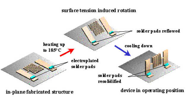
Microwave inductors suffer from considerable losses due to substrate coupling when integrated on low resistivity substrates. With MEMS, new solutions to this problem are possible, since MEMS fabrication methods allow the creation of increased physical separation between coil and substrate compared to genuinely planar fabrication techniques. Our approach is based on a self-assembly technique using the surface tension of molten solder in order to rotate in-plane fabricated inductors into their operating position perpendicular to the substrate. This approach allows us to separate the inductor coil by several hundred microns from the substrate, and at the same time the orientation of the magnetic field is rotated in a direction parallel to the substrate, further reducing coupling effects.
 |
|---|
| Self-assembly principle for 3-D inductor fabrication. |
The process that has been developed is fully parallel and compatible with any type of substrate thanks to the use of photoresist as sacrificial material and the low peak temperature used. Meandered inductors have been fabricated on 5 ?cm Si substrates, with inductances of 1 - 3 nH. These show a very significant increase in quality factor from around 4 (for planar devices) to over 30 (for upright standing devices). Self-resonance frequencies are also greatly increased.
Spiral inductors have also been fabricated, with inductances of 5 nH. These are expected to yield even higher Q for the same chip area. We are currently developing improved processes for self-assembled inductors and other devices using different metal layers, and are transferring the capability to a semiconductor foundry (Semefab Ltd.) for commercialisation.
 | |
|---|---|
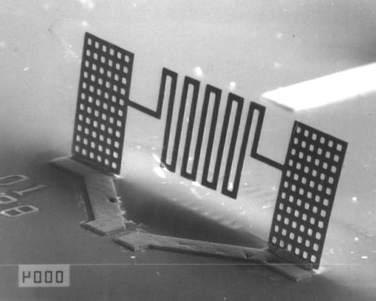
| 3-D micro-inductors fabricated by surface tension self-assembly. | |
 |
|---|
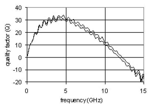
| Q vs. frequency for 3 turn out-of-plane meanders after de-embedding of feed lines. |
Eric Yeatman, Tzern Tzuin Toh, Paul Mitcheson
Energy harvesting from moving structures has been a topic of much research, particularly for applications in powering wireless sensors. Most motion energy harvesters are inertial, drawing power from the relative motion between an oscillating proof mass and the frame from which it is suspended, and we have ongoing work on such devices . For many important applications, including tire pressure sensing and condition monitoring of machinery, the host structure undergoes continuous rotation; in these cases, previous energy harvesters have typically been driven by the associated vibration. Recently we have shown that rotational motion can be used directly to harvest power, and that conventional rotating machines can be easily adapted to this purpose.
 |
|---|
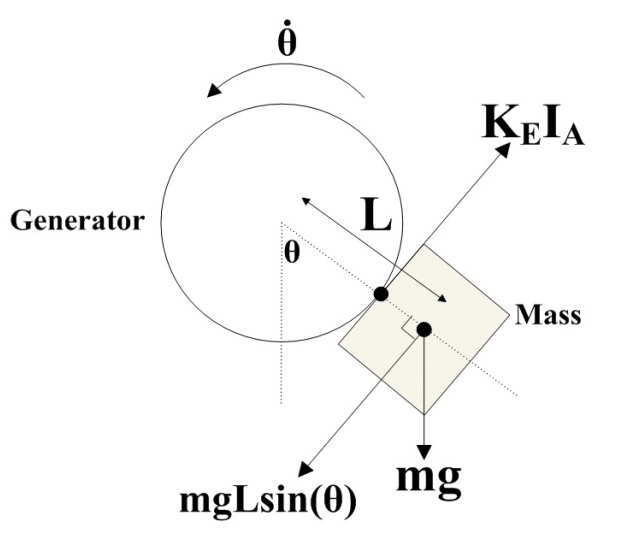
| Fig. 1. Schematic diagram showing operating principle. |
All mechanical to electrical transducers rely on the relative motion of two generator sections. Inertial generators are valuable because they need only be attached to one moving point; the other section is un-anchored and its inertia is used to restrict motion. For rotational host motion at constant speed, inertia cannot be used. Our device instead uses gravitational acceleration to provide the counter-force (Fig. 1). The housing (stator) of a rotating generator is attached to any point on the rotating structure, and an off-centered mass is attached to the rotor. When power is drawn, magnetic torque rotates the rotor along with the stator and host; this creates a gravitational torque which fixes the angle. Stable generation is limited to magnetic torques up to mgL, above which the rotor flips over, so the maximum power is Pmax = mgLw, with w the angular rotation rate.
| Fig. 2. Schematic of experimental apparatus. |
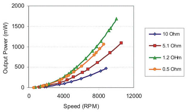
In a first demonstration, a small DC motor (length and diameter 38 and 28 mm respectively) was used as the generator, with the rotor, rather than the stator, coupled to the rotation source (a larger DC motor) for convenience (Fig. 2). The gravitational torque was provided by a 20 g mass attached to the stator, offset by L = 19 mm. Magnetic torque was varied by changing the load resistance RL, with the maximum torque (and power) obtained when RL was matched to the armature resistance (≈ 1.1 Ohm). The output powers are shown in Fig. 3; over 1 W could be easily obtained. Currently we are building dynamically adaptive power conversion circuits, to provide maximum power at fixed voltage, regardless of generator speed.
 |
|---|
| Fig. 3. Measured powers for load resistance values as indicated. |
Stepan Lucyszyn
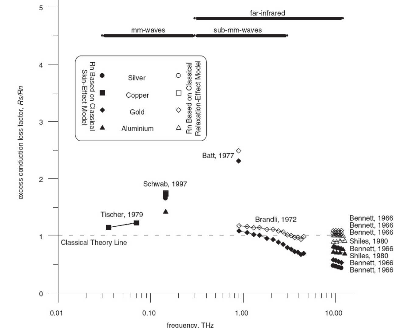
In this work, measurement and modelling strategies have been investigated in detail to determine the surface impedance of normal metals for terahertz frequencies at room temperature. In one study, experimental measurements that suggested the possibility of anomalous room-temperature conduction losses were examined between DC and 12.5 THz. It was found that the classical relaxation-effect model was still valid up to these frequencies. In another study, an elaborate semiclassical model to describe anomalous excess conduction losses at room temperature was found to be completely erroneous. In order to create accurate analytical models, it is important to develop semiclassical modeling strategies or develop quantum mechanical treatments. To this end, and for the first time, various approaches to the modeling of normal metals at room temperature have been undertaken. It has been found that a number of well-know modelling approaches have severe limitations to general applications.
 |
|---|
| Survey of measured excess conduction losses at room temperature |
When the findings from these investigation are combined, any myth associated with anomalous behaviour at room temperature can be finally dispelled; the relaxation-effect model is sufficiently accurate to describe the natural behaviour of normal metals at room temperature. It has already been shown that measured data up to 12.5 THz actually fits the classical relaxation-effect model quite well. This is good news for those working between circa 30 GHz and 12 THz. For example, within future measurement systems, the mathematically simple Drude model can be used to characterize the surface impedance for calibration standards (with accurate values for only o and being needed by the metrologist). This approach would lead to much more accurately calibrated sub-mm-wave measurement systems. For even greater accuracy, the complicated semiclassical approach based on the work of Reuter and Sondheimer are recommended, especially when modelling is to be undertaken for applications well below room temperature.
Eric Yeatman, Andrew Holmes, Richard Syms
Martin Geear, Alan Finlay (Microsaic Systems Ltd.)
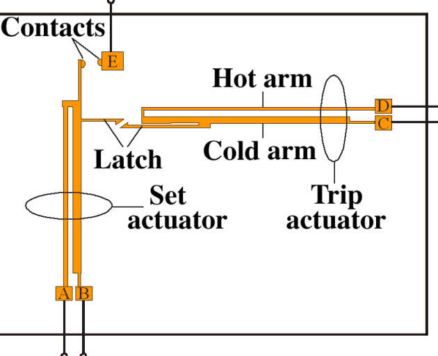
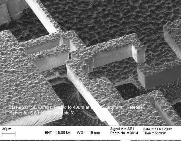
We have demonstrated electromechanical circuit breakers based on MEMS structures. The devices use laterally moving thermal actuators to set and trip low-resistance contacts. The actuators are fabricated from electroplated Ni, on Si substrates, with Au-Co contact layers. Trip currents of 300 mA are obtained, with contact resistances below 1 Ohm. Rapid tripping (below 50 ms) is achieved, even for modest over-current levels, and sensitivity to ambient temperature is much less than for positive temperature coefficient (PTC) devices typically used for over-current protection in electronics applications. These MEMS devices offer an ultra-miniature, potentially low cost solution for circuit protection applications at low currents, where a high degree of system control is desired.
 |
|---|
| Schematic of electrothermal latching MEMS circuit breaker |
 |
|---|
| Latch region of a prototype circuit breaker fabricated in electroplated metal on silicon. |
Richard Syms, Michael Larsson
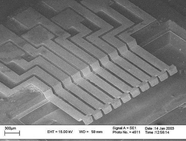
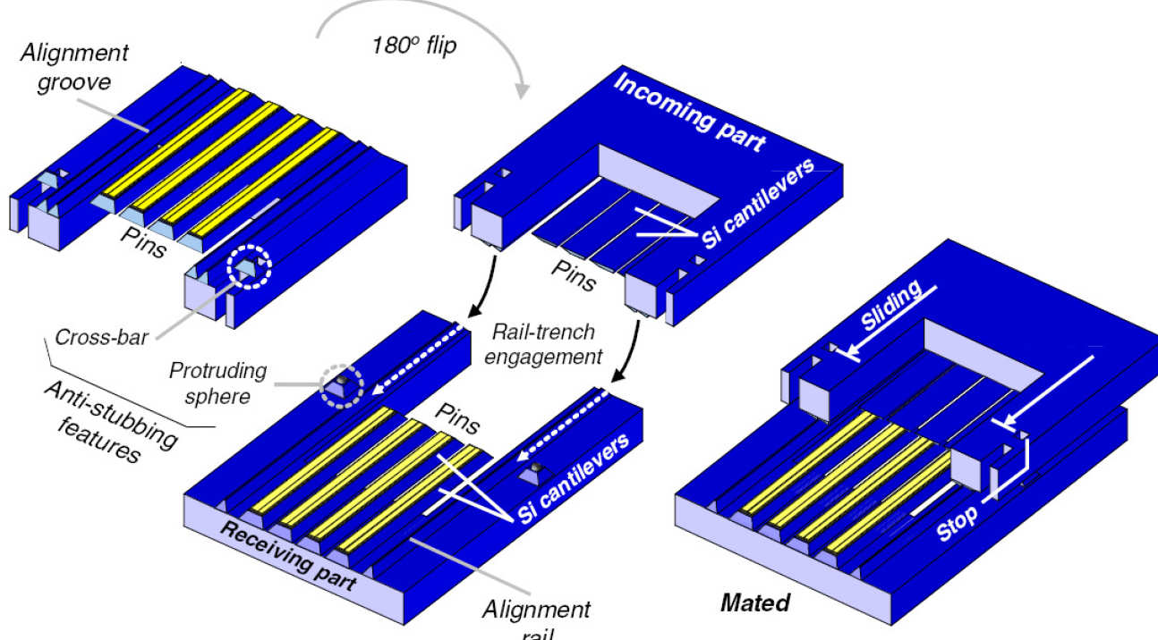
We have developed a MEMS in-line separable connector containing features for precision self-alignment. The concept relies on sliding connection between female and male halves to induce vertical deflections of a set of flexible conductors and establish stable electrical contacts. Electro-deposited photoresist is used to fabricate thick, non-planar conductors, shaped by a silicon substrate that has previously been terraced by anisotropic etching. Further etched features ensure transverse and vertical self-alignment between conductor elements during mating. Prototype 10-way connectors have been demonstrated with 200 µm wide conductors on a 250 µm pitch. Mechanical reliability of contacts during repeated mating and de-mating has been investigated, and initial measurement of contact resistance has given an encouraging value of 30 milliohms.
 |
|---|
| Female half of self-aligning MEMS electrical connector |
 |
|---|
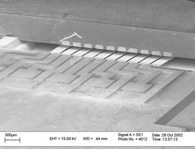
| Assembled connector, showing male half on top of female half. |
 |
|---|
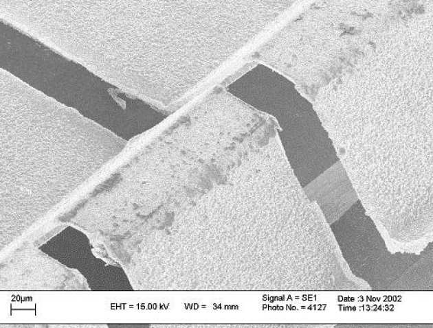
| Connector tongues after repeated mating and demating. |
Tim Green, Paul Mitcheson, Bernard Stark (Control and Power Group)
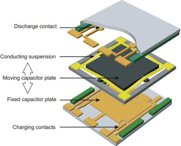
Energy scavenging from the ambient environment is a possible way to power small devices without the lifetime restrictions of batteries. Motion and vibration are one possible source of such energy, and a vibration-powered micro-engineered electrical generator can potentially be integrated with electronics, for example in a miniature sensor node. We are particularly interested in medical and related applications where human body motion is the source, and this presents particular challenges because of the very low frequencies that are involved. To overcome this we have originated a new class of devices, parametric generators, which move nonlinearly; these not only can produce more power than resonant devices at low frequency, but are also better suited to sources of variable and/or broad spectral content.
 |
|---|
| Schematic of microengineered electrostatic generator. |
A schematic of our prototype device is shown above. This is based on the electrostatic force between the plates of a variable capacitor – as the plates are forced apart by the external motion, work is done against this force, which results in increasing voltage on the moving plate. At the maximum separation, the energy can be extracted. Work is also underway to fabricate power electronic circuits for efficient conversion of this energy to a low-voltage, low-output-impedance supply. The project is a collaboration between our group and the Control and Power Group in this department.
 |
|---|
| Prototype generator. Active plate area is c. 1 x 1 cm. |
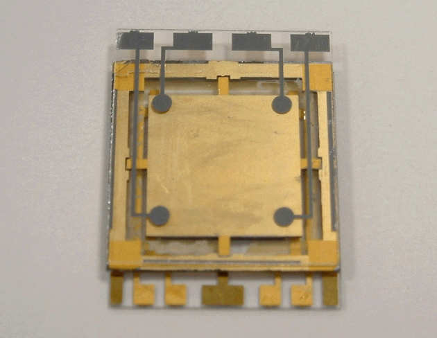
In this project we are developing mm-scale axial-flow turbines that can generate electrical power when placed in an air-stream or other gas flow. The axial-flow geometry is chosen because it allows operation at relatively high flow rates and low pressure heads. Applications are envisaged in areas such as wireless flow sensing and micropower generation.
Current designs are based around a 13 mm-diameter polymer rotor with embedded permanent magnets. The rotors are formed by a combination of UV lithography and excimer laser micromachining, with the laser being used to define the required 3D blade profiles. The rotor is mounted between silicon stator parts carrying multi-layer electroplated copper coils. In addition to producing a range of novel microengineered devices, the project will address more general issues relating to assembly of complex microsystems and implementation of bearings.
The project is funded by EPSRC, and is a collaboration between Imperial College London, Heriot-Watt University, and four industrial partners.
 |
|---|
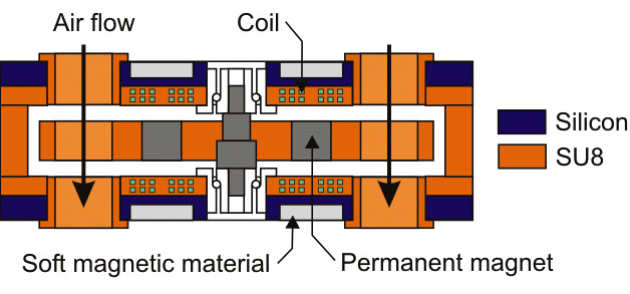
| Cross-sectional view of axial-flow turbine |
 |
|---|
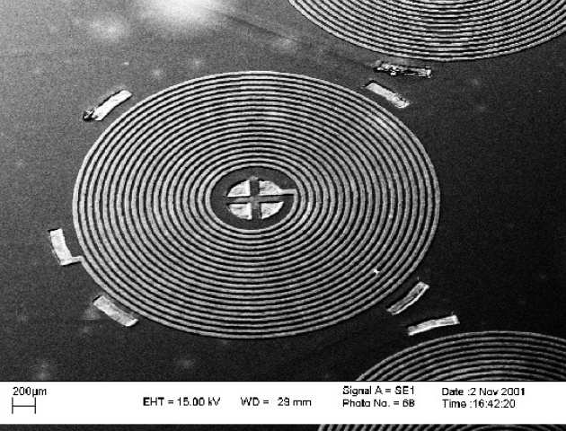
| Multi-layer electroplated copper coils on a silicon stator |
 |
|---|
| Polymer rotor formed in SU8 by UV lithography and laser micromachining |
 |
|---|
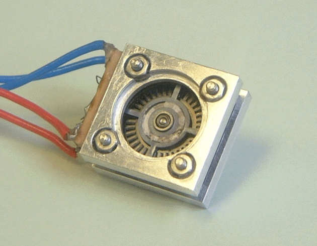
| Prototype axial-flow turboelectric generator |
Stepan Lucyszyn, Hong W. Jiang, Joo-Young Choi
Kenichi Miyaguchi (Mitsubishi Electric, Japan)
Ian D. Robertson (U. of Leeds)
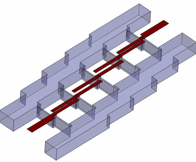
Gavin Fisher and Anthony Lord (Cascade Microtech)This work introduces a new concept for implementing millimeter-wave filters intended for monolithic integration. The approach uses silicon micromachining and wafer bonding techniques to create inverted-microstrip transmission lines in air and RF-coupled cantilevers. A 3rd order filter demonstrated a measured insertion loss of only 0.54 dB at 76.5 GHz. Simple MEMS tuning of 60 GHz coupled-line resonators has also been demonstrated for the first time. This work could form the basis for a new type of low loss tunable distributed-element RF MEMS filter technology for millimeter-wave applications.
 |
|---|
| Isometric illustration of the basic inverted-microstrip filter |
 | |
|---|---|
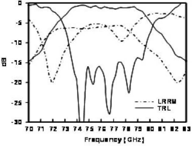
| SEM view of complete lower support substrate for the 110 GHz filter and measured passband insertion and return loss responses for a 76.5 GHz filter | |
 |
|---|
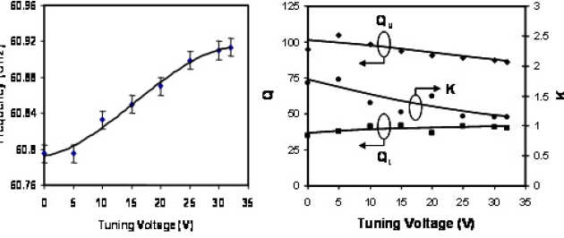
| Resonant frequency vs. tuning voltage for a 60 GHz loaded resonator and extracted values for loaded and unloaded Q factors and coupling coefficient vs. tuning voltage |
Michael P. Larsson and Richard R.A. Syms
A micromachined separable RF connector has been developed using low-resistivity silicon as the substrate material. The design is based around a two-part device, containing pins capable of deflections perpendicular to the substrate plane. Thick SU-8 dielectric is used to reduce lossy substrate coupling and mechanical interlocking is introduced to ensure robust attachment to the substrate during fabrication and in service. Anisotropic wet etching is used to generate alignment features, which allow precise self-alignment between respective parts during mating. Test components were fabricated to allow single-sided probing, revealing a dc contact resistance of 44 milliohms and an insertion loss of 3.5 dB at 8.5 GHz; the latter being stable over at least 100 mating cycles. The insertion loss effectively represents the response of two connector pairs in series, leading to a value of approximately 1.8 dB for a single pair. Isolation between adjacent 100 micron pitch lines is >35 dB at 8.5 GHz, indicating good crosstalk rejection between neighbouring pins. The concept is amenable to meet the future needs of high-density, high-frequency connectors, enhancing the options for integrating MEMS devices with CMOS circuitry.
 |
|---|
| Multi-pin RF separable connector and means of self-aligned connection |
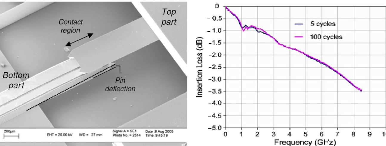 |
|---|
| Single-pin connector in a mated pair and corresponding measured insertion loss |